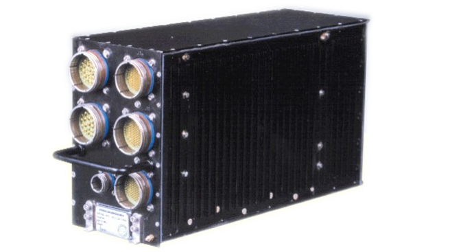
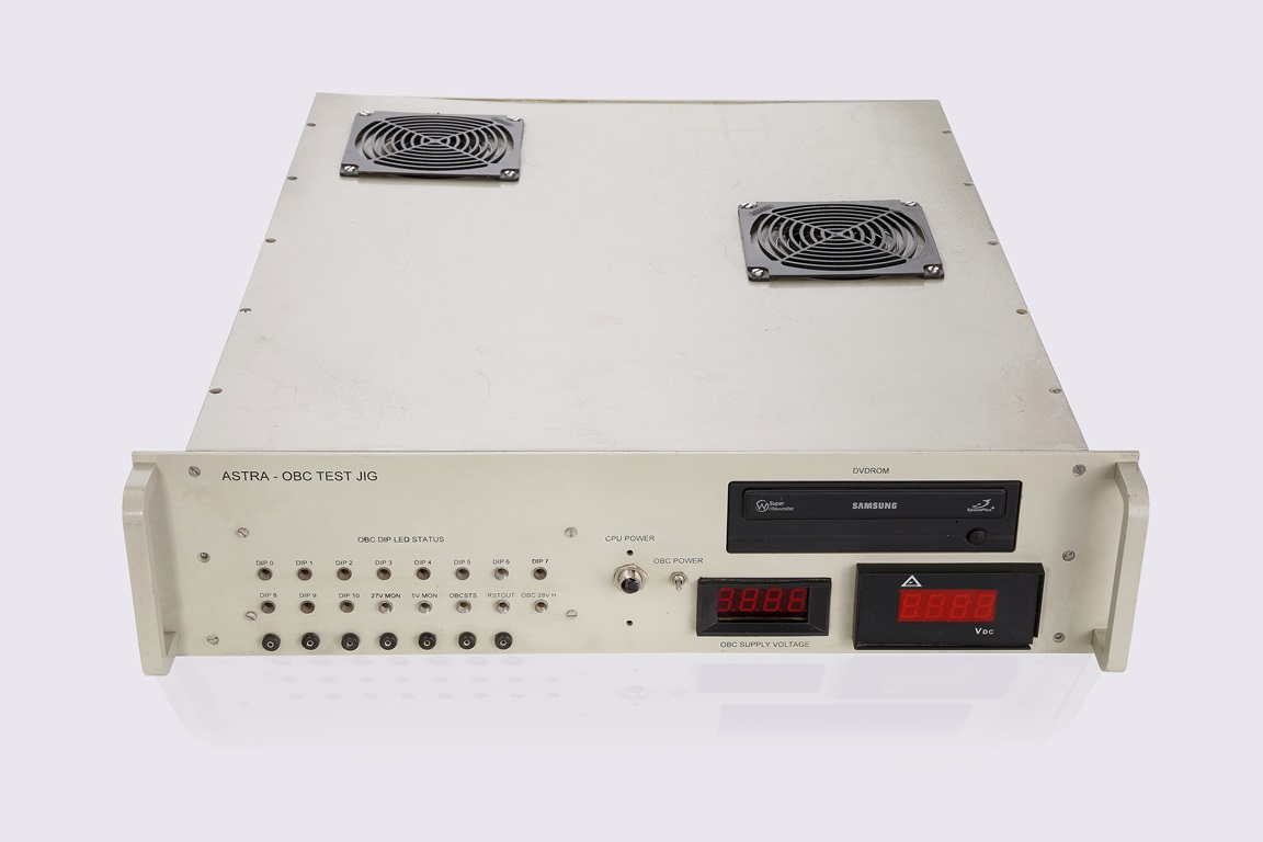
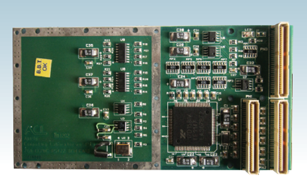
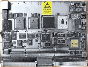
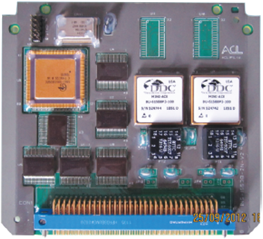
This system is available in two versions, one based on Intel 87C196 CPU and the other with Motorola’s 68332 Micro-Controller. The resources include 88 DIPs, 100 DOPs, 48 Analog Inputs, 12 Analog Outputs, 4 RS-422 channels & one MIL-STD-1553B interface.
Two versions
87C196 Microcontroller based 68332 Microcontroller based.
Interfaces
Digital inputs - 88 Nos. Active (opto isolated), Passive (opto isolated)
Digital outputs - 100 Nos.
Analog inputs - 48 Nos.
Analog outputs - 12 Nos.
MIL-STD-1553B-SERIAL bi-directional communication interface- 1 No.
Point to point serial communication RS-422 - 4 Nos.
Applications
Being used as data acquisition systems for National programmes.
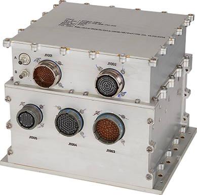
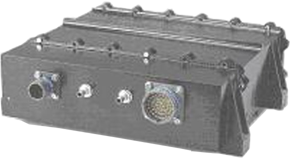
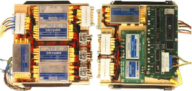
The Stores Interface Box (SIB) is an LRU, which is required to function in a high reliability safety critical environment. Its function is to control a number of other subsystems based on commands received from two open architecture computers over 1553B Buses. The SIB is configured as dual redundant hardware including power supply to enhance the reliability. The SIB is packaged in a ½ Air Transport Rack (ATR) size enclosure with overall dimensions L=355mm, W=124mm, H= 194mm. The SIB consists of 3 PCBs of size 233.35 X 160 mm(6U Double Euro) in the main card cage and a set of 2 smaller PCBs of size 75 mm X160 mm and 65mm X 160mm in the side compartment which houses the ARINC S700 connector.The 3 PCBs in the main card cage plug into a 3 slot VME back-plane with P0, P1 & P2 connectors. The input and output signals to/from the SIB through a combination of Round shell MIL 38999, ARINC S700 Rack & Panel, and tri-axial SMA connectors. In addition set of 34 electro-mechanical relays, DC-DC converter modules and associated RF filters to derive the required operating voltages for the various circuits (+5V and isolated +28V) from the 28VDC input equipment supply also in the Rack.The SIB is dissipate around 40 watt depending on the loading and duty cycle. Weight of the unit is around 10Kg. Applicable standards are MIL-STD-810D and MIL-STD-461.
Duis aute irure dolor in reprehenderit in voluptate velit esse cillum dolore eu fugiat nulla pariatur. Excepteur sint occaecat cupidatat non proident, sunt in culpa qui officia deserunt mollit anim id est laborum.
Environmental Specifications
Vibration: As per MIL-STD-810D Shock : As per MIL-STD-810D Radiation Susceptibility : As per MIL-STD 461C, 462 & Compatibility. Operating Temperature : -40° to 65° C Storage Temperature : -55° to 85 ° C Damp Heat : As per MIL-STD-810D Electrical Supply Sensitivity: As per MIL-STD-704D
Electrical Specifications :The Power Supply to all the cards in SIB are derived through EMI/EMC 461C compliance Power Filter and DC-DC Converter.
Grounding:The internal Supply returns are terminated to equipment sub-star to which all ground lines (Digital, Analog).The general Grounding, Shielding, Isolation Filter etc., are in accordance with EMI/EMC norms. Bonding Resistance measurement lug is provided on front face of the LRU.Earthing :
Single Point Earthing outside the Box. All the cards are electrically isolated with respect to the Chassis Ground . Resistance to ground > 1M Ohms Insulation between any line and chassis > 1M Ohm
Mechanical Specifications:
Material :Aluminium 6061 avionics grade alloy
Mounting:The Unit does not require any special guide or fixtures for installation and does not have installation location constraints.
Physical:
Size : ½ ATR (L=355mm, W=124mm, H=194mm) Weight (loaded with PCBs ) : 11Kg (Maximum)Thermal Specifications:
Cooling : Conductive Cooling (No Fans) PCBs : Metal-Core
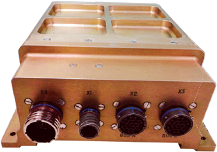
This package is one of the critical avionic packages. The unit receives commands from onboard computer over 1553B bus and is responsible for switching relays, monitoring their status, sending command voltages to control systems, providing excitation supply to pressure transducers, conditioning received signal voltages and measuring parameters like system pressures and battery voltages.
Overview
Compliance to MIL-STD-461E & MIL-STD-810FThis package is one of the critical avionic packages. The unit receives commands from onboard computer over 1553B bus and is responsible for switching relays, monitoring their status, sending command voltages to control systems, providing excitation supply to pressure transducers, conditioning received signal voltages and measuring parameters like system pressures and battery voltages.
Specifications
CCSC Unit consists of CCSC Relay section and CCSC MIU.
CCSC Relay Section:
High Current Relays
Solid State Relays 25A : 1 No.
3PDT 25A Latch Relay : 1 No.
4PDT 10A Latch Relay : 2 Nos.
4PDT 10A Non Latch Relay : 2 Nos.
2PDT 5A Non Latch Relay : 4 Nos.
2PDT 10A Latch Relay : 3 Nos .
CCSC Relay Power Supply Specifications:
Input : 18-36V
Outputs : 3 Nos.
V1: +5V @ 5A
V2: +15V @1A
V3: -15V @ 1A
CCSC MIU Section :
Processor: Vertex-II Pro Embedded PowerPC 405
Memory :
SRAM : 256K x 32
FLASH : 256K x 32
Analog Inputs :
No. of channels : 22 Nos. [15 Nos(Single ended),7 Nos. (Differential) ]
Voltage Range : -10V to +10V
Resolution : 16-Bit
Conversion Time : 4 µs
Isolation : Optical
Analog Outputs :
No. of channels 4 Nos.
Voltage Rang :e -10V to +10V
Resolution : 12 bits
Settling Time : 8 µs
Isolation : Optical
Digital Inputs :
No.of channels : 64 Nos.
Isolation : Optical
Input Voltage Range : 5V
Digital Outputs :
No.of channels : 64 Nos.
Isolation : Optical
Driving Voltage Range : 28 V
Driving Capacity : 500 mA
1553B Interface :
No. of Dual Redundant Channels: 1Channel (Bus A and Bus B)
Memory : 64 K x 16 / 4K x 16
Interface Chip : BU 61688 / 61588
RS-422 Interface :
No. of Channels: 1 No.
CCSC MIU Power Supply Specifications:
Input : 18-36V
Outputs : 7 Nos.
V1: +5V @ 3A
V2: +5V @ 2A
V3: +3.3V @ 7A
V4: +15V @ 0.9A
V5: -15V @ 0.9A
V6: +28V @ 1.25A
V7: +28V @ 1.25A
Overview : Compliance to MIL-STD-461E & MIL-STD-810FThis package is one of the critical avionic packages. The unit receives commands from onboard computer over 1553B bus and is responsible for switching relays, monitoring their status, sending command voltages to control systems, providing excitation supply to pressure transducers, conditioning received signal voltages and measuring parameters like system pressures and battery voltages.
CCSC Unit consists of CCSC Relay section and CCSC MIU.
CCSC Relay Section:
High Current Relays
4PDT 10A Latch Relay : 4 Nos.
4PDT 10A Non Latch Relay : 5 Nos.
2PDT 5A Non Latch Relay : 16 Nos.
CCSC Relay Power Supply Specifications:
Input : 18-36V Outputs : 3 Nos. V1: +5V @ 5A V2: +15V @1A V3: -15V @ 1A
CCSC MIU Section :
Processor: Vertex-II Pro Embedded PowerPC 405
Memory : SRAM :256K x 32FLASH :256K x 32
Analog Inputs :No. of channels :22 Nos. [15 Nos(Single ended),7 Nos. (Differential) ]Voltage Range :-10V to +10VResolution :16-BitConversion Time :4 µsIsolation :Optical
Analog Outputs :No. of channels:4 Nos.Voltage Range :-10V to +10VResolution :12 bitsSettling Time :8 µsIsolation :Optical
Digital Inputs :No.of channels :64 Nos.Isolation :OpticalInput Voltage Range :5V
Digital Outputs :No.of channels :64 Nos.Isolation :OpticalDriving Voltage Range :28 VDriving Capacity :500 mA
1553B Interface :No. of Dual Redundant Channels:1Channel (Bus A and Bus B)Memory :64 K x 16 / 4K x 16Interface Chip :BU 61688 / 61588
RS-422 Interface :No. of Channels:1 No.
CCSC MIU Power Supply Specifications:
Input : 18-36V
Outputs : 7 Nos.
V1: +5V @ 3A
V2: +5V @ 2A
V3: +3.3V @ 7A
V4: +15V @ 0.9A
V5: -15V @ 0.9A
V6: +28V @ 1.25A
V7: +28V @ 1.25A
PENDING
PENDING 1
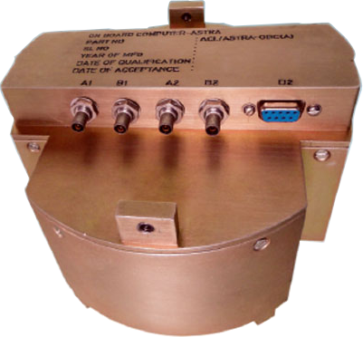
On Board Computer is a ruggedized computer designed to carry out various functions, viz. control, guidance, monitor the health of sub systems. The OBC interacts with Receiver and Telemetry using 1553B bus. In addition OBC also has other interfaces like Discrete Outputs interface and control system interface (Analog I/O).OBC operates on 28 V DC input supply.
The On Board Computer is based on distributed architecture system and real time data exchange is required between various subsystems. OBC is based on ADSP21060 processor. It has two channels of dual redundant MIL-STD-1553B buses.
CPU Dual ADSP-21060LCWZ-160 processors with a clock frequency of 32 MHz.
Memory SRAM 512K x 32 bits,
-FLASH1 4M x 8 bits,
-NVRAM 32K x 8 bits
Timers Two programmable timers of minimum resolution 2µsec
I/O Specifications
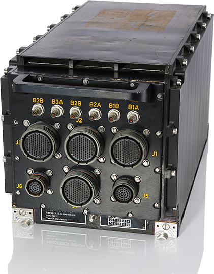
The ¾ Aviation Transport Rack is a LRU, which is required to function in a highly reliable and safety critical environment. The ¾ ATR is a Ruggedized Mechanical chassis. The basic concepts of focus are the inter-changeability of the LRU, high levels of Thermal Management, easy mode of operation and maintenance.
Unit is based on Intel-80486 CPU operating at 64Mhz speed. It communicates with external units through MIL-STD-1553B Channel. It has 4 MB of Flash and 2 MB of SRAM along with 32 discrete inputs/outputs, three serial RS-422 interfaces, 16 analog inputs & 8 analog outputs, 6 timers, and One RS-232 interface. The system is a self-contained unit and operates with DC input of 28V. The unit has circular connectors on its back panel for external interfaces. The MIL-STD-1553B interface is provided through BJ-77 Connectors. Provision for future growth potential is provided though addition of a mezzanine connector. Additional interfaces can be added through the addition of mezzanine cards for custom-built requirements. State of the art components / technology are used for the design.
The required power supplies in the system are derived using DC-DC converters and other electronics with 28V DC input. The following supplies are generated: PCB: Size: 156mm x 132mma) + 5V, 8A b) +15V, 1A c) -15V, 1A
The system comes with advanced monitor software along with powerful diagnostic software to test each and every resource exhaustively. The system also comes with highly validated 1553B library functions.
The unit has one CPU card, one I/O card, one Power supply module and a Motherboard. Specifications of CPU, I/O and Power Supply modules are given below. The Mother board and mechanical chassis can be configured based on application
CPU card has the following features:
Sample text. Click to select the text box. Click again or double click to start editing the text.
write product review