Apollo Computing Laboratories (P) LtdInnovation is our Tradition
+91-40- 27141522, 27141533
MIL-STD-1553B/1773 Solutions ISA Based BISA-ISA-1553B
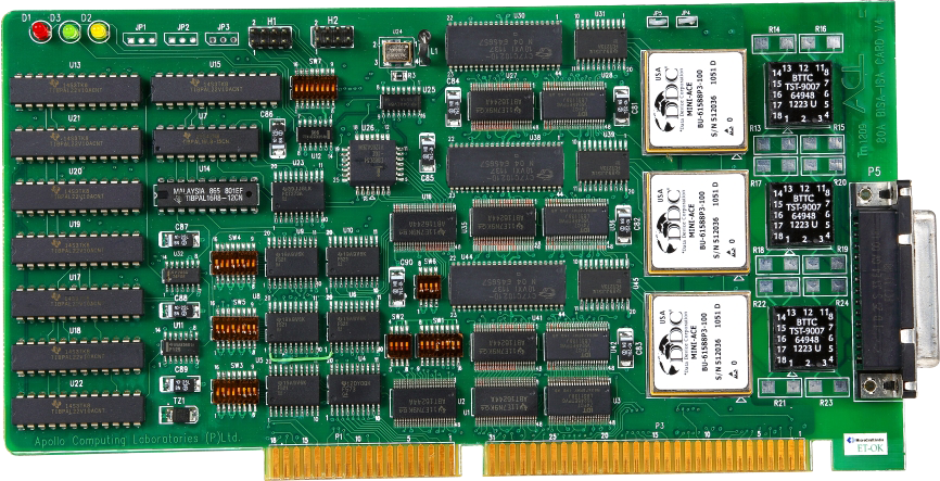
The BISA-ISA-1553B is a ISA bus based add-on card that can be hosted on any PC (PC-AT/386/486/Pentium) bus interface providing three independently configurable dual redundant Bus Controller/Remote Terminal/Monitor (based on DDC`s BU-61580 or 61588 Mini-ACE) on forming to MIL-STD-1553B Notice-2. The design supports a single PC hosting multiple modules – limitations being available system free slots and computational power of PC host. Thus, the BISA-ISA-1553B is an excellent choice for dynamic real-time avionics simulations. The on-board double buffered dual port memory facilitates parallel message preparation & transfers, increasing the effective throughput. The BISA-ISA-1553B comes with Bus Libraries, a powerful C-callable library routines to access the bus at various levels of abstraction, hardware complexities being transparent to the user. The module is supported by an user friendly, menu driven, configurable software package under Windows-NT environment, with higher level functions like data formatting, logging, display etc. The performance of BISA-ISA-1553B is far superior to solutions offered by others around the globe. The board supports novel Transmitter shutdown feature (in S/W and H/W) in BC mode.
Upto three independent dual redundant BC/RT/MT Channels, based on DDC's BU-61580 or BU-61588 Mini-ACE on one PC-AT/386/486/Pentium system free ISA slot.
Supports full MIL-STD-1553B Notice-2.
Supports all 1553B message formats and mode-codes.
On board time-tag counter.
Software programmable RT Command illegalization logic.
RT Sub-address circular buffers to support bulk data transfers.
Optional separation of RT broadcast data.
Each channel supports double buffered dual ported 32 K X 16 bit memory for preparation and transfer.
Programmable RT address.
High performance.
Novel Transmitter Shut-down feature in BC mode.
Scalable architecture supporting intra system expandability.
Multiple bus simulation on single PC-AT/386/486/Pentium system.
Ideal for real-time avionics simulation.
Programmable real-time clock.
Two programmable Timers.
Built in test s/w for diagnostics.
Bus Libraries: Powerful C-callable routines to support BC/RT/MT functions.
Powerful message debugging facility.
Typical Inter-message gap of 10 micro seconds.
Unprecedented Flexibility.
Optional : Real Time OS Libraries available as optional.
C-Callable Routines For BC/RT/MT for BISA-ISA-1553B Add-on card
The following are the major sub-groups of the library functions available with BISA-ISA-1553B ISA bus based add-on card.
The `C` callable libraries support all the functions of BU-61588 (provides full compatibility to older version chips BU-61580, BU-65170 ACE).
BISA-ISA-1553B-1 : Single Node ISA 1553B add-on card.
BISA-ISA-1553B-2 : Two Node ISA 1553B add-on card.
BISA-ISA-1553B-3 : Three Node ISA 1553B add-on card.
PCI Based BISA-PCI-1553B PCI Bus Based MIL-STD-1553B Add-On Card
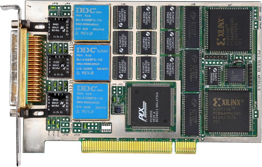
The BISA-PCI-1553B is a PCI bus based add-on card that can be hosted on any PC (PC-AT/386/486/Pentium/i3/i5/i7) bus interface providing three independently configurable dual redundant Bus Controller/Remote Terminal/Monitor (based on DDC`s BU-61588/688 Mini-ACE) conforming to MIL-STD-1553B Notice-2, along with four RS-422 channels and eight TTL compatible DIOs. The design supports a single PC hosting multiple modules - limitations being: available system free slots and computational power of PC host. Thus, the BISA-PCI-1553B is an excellent choice for dynamic real-time avionics simulations. The on-board double-buffered dual port memory facilitates parallel message preparation & transfers, increasing the effective throughput. The BISA-PCI-1553B card comes with Bus Libraries, powerful C-callable library routines to access the bus at various levels of abstraction, hardware complexities being transparent to the user. Optionally the module is supported by an user friendly, menu driven, configurable software package under Windows-NT/XP/WIN-7 environment, with higher level functions like data formatting, logging, display etc. The performance of BISA-PCI-1553B is far superior to solutions offered by others around the globe. The board supports novel Transmitter shutdown feature (in S/W and H/W) in BC mode.
Upto three independent dual redundant BC/RT/MT Channels, based on DDC's BU-61588/688 Mini-ACE on one PC-AT/386/486/Pentium/i3/i5/i7 system free PCI slot.
Supports full MIL-STD-1553B Notice-2.
Supports all 1553B message formats and mode-codes.
On board time-tag counter.
Software programmable RT Command illegalization logic.
RT Sub-address circular buffers to support bulk data transfers.
Optional separation of RT broadcast data.
Each channel supports double buffered dual ported 32 K X 16 bit memory for preparation and transfer.
Programmable RT address.
High performance.
Novel Transmitter Shut-down feature in BC mode.
Scalable architecture supporting intra system expandability.
Multiple bus simulation on single PC.
Ideal for real-time avionics simulation.
Programmable real-time clock.
Two programmable Timers.
Built in test s/w for diagnostics.
Bus Libraries: Powerful C-callable routines to support BC/RT/MT functions.
Parmon: Parametric Monitoring Software, a user friendly Menu driven Software is available for XP/Win7 and also available for Windows-NT 4.0 (optional).
Powerful message debugging facility.
Typical Inter-message gap of 10 micro seconds.
Unprecedented Flexibility.
Optional : Real Time OS Libraries available as optional.
C-Callable Routines For BC/RT/MT for BISA-PCI-1553B Add-on card
The following are the major sub-groups of the library functions available with BISA-PCI-1553B PCI bus based add-on card.
The `C` callable libraries support all the functions of BU-61588 (provides full compatibility to older version chips BU-61580, BU-65170 ACE).
BISA-PCI-1553B-1 : Single Node PCI 1553B add-on card.
BISA-PCI-1553B-2 : Two Node PCI 1553B add-on card.
BISA-PCI-1553B-3 : Three Node PCI 1553B add-on card.
PCI Based APOORVA-1553B Two Node BC/RT/MT Add-On Card
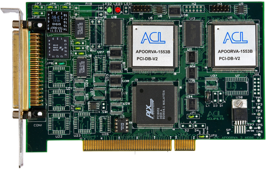
The APOORVA-1553B BCRTMT is a PCI bus based Two Node MIL-STD-1553B add-on card which can be hosted on any PC (PC-AT/386/486/Pentium/i3/i5/i7) PCI bus interface providing up to Two independently configurable buses. Each Bus provides simultaneously dual redundant BC/RT/MT or BC, RT & MT (based on ACL’s APOORVA-1553B Core) nodes conforming to MIL-STD-1553B Notice-2. The design supports a single PC hosting multiple modules - limitations being: available system free slots and computational power of PC host. Thus, the APOORVA-PCI-DUAL-BCRTMT-1553B is an excellent choice for dynamic real-time avionics multiple bus simulations. The on-board double buffered dual port memory facilitates parallel message preparation & transfers, increasing the effective throughput.
The APOORVA-1553B Based BCRTMT comes with Bus Libraries, powerful C-callable library routines to access the bus at various levels of abstraction, hardware complexities being transparent to the user. Optionally the module is supported by an user friendly, menu driven, configurable software package under Windows-XP/Win7 environment, with higher level functions like data formatting, logging, display etc. The performance of APOORVA-1553B Based BCRTMT is far superior to solutions offered by others around the globe.
Apoorva provides a unique facility to the user to enable or disable the messages in the Frame.
Up to Two independently configurable buses. Each Bus provides simultaneously dual redundant BC/RT/MT or BC, RT & MT nodes (based on options chosen) conforming to MIL-STD-1553B Notice-2.on a PC with free PCI slot.
Supports full MIL-STD-1553B Notice-2.
Supports all 1553B message formats and mode-codes.
On board time-tag counter.
RT Sub-address circular buffers to support bulk data transfers
Optional separation of RT broadcast data.
Each channel supports double buffered dual ported 7.5 K X 16 bit memory for preparation and transfer.
Programmable RT address
High performance.
Two on-board timers.
Typical Inter-message gap of 10 micro seconds. Optionally 4.20 micro seconds.
Scalable architecture supporting intra system expandability.
Multiple bus simulation on single PC.
Ideal for real-time avionics simulation.
Bus Libraries: Powerful C-callable routines to support BC/RT/MT or BC, RT & MT functions.
Powerful message debugging facility.
Unprecedented Flexibility: Minor Frame Time Programmable in steps of 1.0 milli seconds accurately along with Minor frame messages loadable in hardware itself to provide accurate real-time performance.
Built in Diagnostic and test S/W for diagnostics.
Parmon: Parametric Monitoring Software, a user friendly Menu driven Software is available for XP/Win7 and also available for Windows-NT 4.0 (optional).
Supported drivers for Windows 2000, Windows XP, Windows 7 and Linux.
Optional : Real Time OS Libraries.
MEMORY
| As BC | 7.5 K words | |
| As RT | 7.5 K words | |
| As MT | 16 K words | |
| Circular Buffer | 15 K words |
With The APOORVA-1553B Based BCRTMT cards, the following Errors can be injected to verify the LRUs and other systems functioning:
Manchester errors
Bit length errors
Word count errors
Bi-phase errors
Sync errors
Gap time introduction etc.
Bus Libraries: The APOORVA-1553B Based BCRTMT PCI bus based add-on card comes with C-callable library functions/routines to utilise the resources of the card.
APOORVA-PCI-SINGLE-BC, RT & MT-1553B: PCI bus based MIL-STD-1553B Single Node Add-on card supporting BC, RT & MT (simultaneously).
APOORVA-PCI-DUAL-BC, RT & MT-1553B: PCI bus based MIL-STD-1553B two Node Add-on card supporting BC, RT & MT (simultaneously) for each bus.
APOORVA-PCI-SINGLE-BC/RT/MT-1553B: PCI bus based MIL-STD-1553B single Node BC/RT/MT Add-on Card.
APOORVA-PCI-DUAL-BC/RT/MT-1553B: PCI bus based MIL-STD-1553B Two Node BC/RT/MT Add-on Card
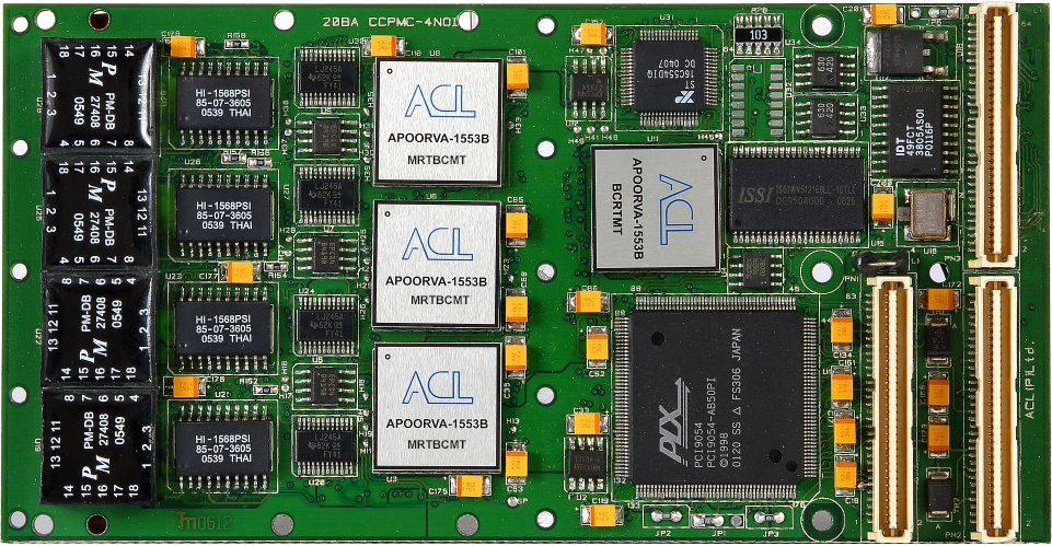
PCI Based APOORVA-1553B Two Node MRTBCMT Add-On Card

The APOORVA-1553B MRTBCMT is a PCI bus based MIL-STD-1553B add-on card and can be hosted on any PC (PC-AT/386/486/Pentium/i3/i5/i7) PCI bus interface providing simultaneously two buses each with dual redundant 31RTs, BC & MT (based on ACL’s Apoorva-1553B Core) nodes conforming to MIL-STD-1553B Notice-2. The design supports a single PC hosting multiple modules - limitations being: available system free slots and computational power of PC host. Thus, the APOORVA-1553B Based MRTBCMT is an excellent choice for dynamic real-time avionics simulations. The on-board double buffered dual port memory facilitates parallel message preparation & transfers, increasing the effective throughput.
The APOORVA-1553B Based MRTBCMT comes with Bus Libraries, powerful C-callable library routines to access the bus at various levels of abstraction, hardware complexities being transparent to the user. Optionally the module is supported by an user friendly, menu driven, configurable software package under Windows-XP/Win7 environment, with higher level functions like data formatting, logging, display etc. The performance of APOORVA-1553B Based MRTBCMT is far superior to solutions offered by others around the globe.
Apoorva provides a unique facility to the user to enable or disable the messages in the Frame.
Provides simultaneously up to two buses each with dual redundant 31RTs, BC & MT (based on ACL’s APOORVA-1553B Core) conforming to MIL-STD-1553B Notice-2 on a PC with free PCI slot.
Supports full MIL-STD-1553B Notice-2.
Supports all 1553B message formats and mode-codes.
On board time-tag counter.
RT Sub-address circular buffers to support bulk data transfers.
Optional separation of RT broadcast data.
Each channel supports double buffered dual ported 7.5 K X 16 bit memory for preparation and transfer.
Programmable RT address.
High performance.
Scalable architecture supporting intra system expandability.
Supports multiple bus simulation on single PC-AT/386/486/Pentium system.
Ideal for real-time avionics simulation.
Built in test S/W for diagnostics.
Bus Libraries: Powerful C-callable routines to support BC, RT & MT functions.
Parmon: Parametric Monitoring Software, a user friendly Menu driven Software is available for XP/Win7 and also available for Windows-NT 4.0 (optional).
Powerful message debugging facility.
Unprecedented Flexibility: Minor Frame Time Programmable in steps of 1.0 milli seconds accurately along with Minor frame messages loadable in hardware itself to provide accurate real-time performance.
Typical Inter-message gap of 10 micro seconds.
Supported drivers for Windows 2000, Windows XP, Windows 7 and Linux.
Optional : Real Time OS Libraries.
| As BC | 7.5 K words | |
| As RT | 7.5 K words | |
| As MT | 16 K words | |
| Circular Buffer | 256 K words |
With The APOORVA-1553B Based MRTBCMT cards, the following Errors can be injected to verify the LRUs and other systems functioning:
Manchester errors
Bit length errors
Word count errors
Bi-phase errors
Sync errors
Gap time introduction etc.
Bus Libraries: The APOORVA-PCI-MRT-BC-MT-1553B PCI bus based add-on card comes with C-callable library functions/routines to utilise the resources of the card.
APOORVA-PCI-SINGLE-MRT-BC-MT-1553B: PCI bus based MIL-STD-1553B Simulator / tester providing Simultaneous 31RTs, BC & MT on single 1553B bus
APOORVA-PCI-DUAL-MRT-BC-MT-1553B: PCI bus based MIL-STD-1553B Simulator / tester providing Simultaneous 31RTs, BC & MT on Two 1553B buses
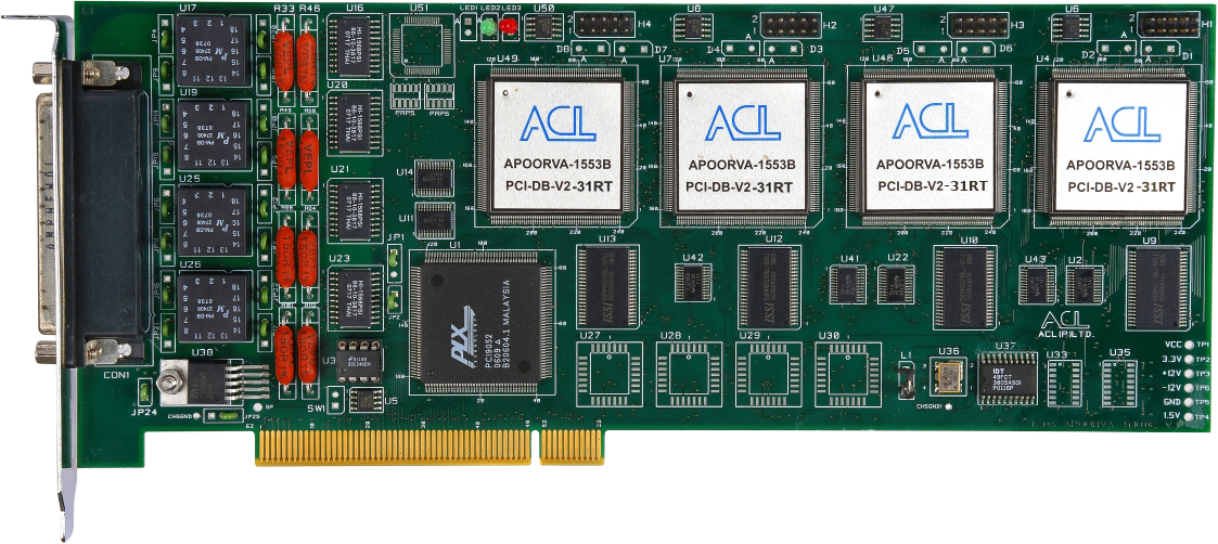
PCI Based APOORVA-1553B FOUR Node BC or RT or MT Add-On Card

PCI bus based Four Node Apoorva MIL-STD-1553B add-on card which can be hosted on any PC (PCAT/386/486/ Pentium/i3/i5/i7) PCI bus interface providing up to Four independently configurable buses. Each Bus provides simultaneously dual redundant BC/RT/MT or BC, RT & MT (based on ACL’s APOORVA-1553B Core) nodes conforming to MIL-STD-1553B Notice-2. The design supports a single PC hosting multiple modules -limitations being: available system free slots and computational power of PC host. Thus, the APOORVA-PCI-FOUR-BCRTMT-1553B is an excellent choice for dynamic real-time avionics simulations. The on-board double buffered dual port memory facilitates parallel message preparation & transfers, increasing the effective throughput.
The APOORVA-1553B Based BCRTMT comes with Bus Libraries, powerful C-callable library routines to access the bus at various levels of abstraction, hardware complexities being transparent to the user. Optionally the module is supported by an user friendly, menu driven, configurable software package under Windows-XP/Win7 environment, with higher level functions like data formatting, logging, display etc. The performance of APOORVA-1553B Based BCRTMT is far superior to solutions offered by others around the globe.
Apoorva provides a unique facility to the user to enable or disable the messages in the Frame.
Provides simultaneously up to two buses each with dual redundant BC, RT & MT (based on ACL’s APOORVA-1553B Core) conforming to MIL-STD-1553B Notice-2 on a PC with free PCI slot.
Supports full MIL-STD-1553B Notice-2.
Supports all 1553B message formats and mode-codes.
On board time-tag counter.
RT Sub-address circular buffers to support bulk data transfers.
Optional separation of RT broadcast data.
Each channel supports double buffered dual ported 7.5 K X 16 bit memory for preparation and transfer.
Programmable RT address.
High performance.
Two on-board timers.
Typical Inter-message gap of 10 micro seconds. Optionally 4.20 micro seconds.
Scalable architecture supporting intra system expandability.
Multiple bus simulation on single PC.
Ideal for real-time avionics simulation.
Bus Libraries: Powerful C-callable routines to support BC/RT/MT or BC, RT & MT functions.
Powerful message debugging facility.
Unprecedented Flexibility: Minor Frame Time Programmable in steps of 1.0 milli seconds accurately along with Minor frame messages loadable in hardware itself to provide accurate real-time performance.
Built in Diagnostic and test S/W for diagnostics.
Parmon: Parametric Monitoring Software, a user friendly Menu driven Software is available for XP/Win7 and also available for Windows-NT 4.0 (optional).
Supported drivers for Windows 2000, Windows XP, Windows 7 and Linux.
Optional : Real Time OS Libraries.
| As BC | 7.5 K words | |
| As RT | 7.5 K words | |
| As MT | 16 K words | |
| Circular Buffer | 15 K words |
With The APOORVA-1553B Based 4 Node BCRTMT cards, the following Errors can be injected to verify the LRUs and other systems functioning:
Manchester errors
Bit length errors
Word count errors
Bi-phase errors
Sync errors
Gap time introduction etc.
The APOORVA-1553B Based 4 Node BCRTMT PCI bus based add-on card comes with C-callable library functions/routines to utilise the resources of the card.
APOORVA-PCI-THREE-BC, RT & MT-1553B: PCI bus based MIL-STD-1553B Three Node Add-on card supporting BC, RT & MT (simultaneously).
APOORVA-PCI-FOUR-BC, RT & MT-1553B: PCI bus based MIL-STD-1553B Four Node Add-on card supporting BC, RT & MT (simultaneously) for each bus.
APOORVA-PCI-THREE-BC/RT/MT-1553B: PCI bus based MIL-STD-1553B Three Node BC/RT/MT Add-on Card.
APOORVA-PCI-FOUR-BC/RT/MT-1553B: PCI bus based MIL-STD-1553B Four Node BC/RT/MT Add-on Card.
PCI Based APOORVA-1553B FOUR Node MRTBCMT Add-On Card
PCI bus based Apoorva Four Node MIL-STD-1553B add-on card which can be hosted on any PC (PC-AT/386/486/Pentium/i3/i5/i7) PCI bus interface providing simultaneously Four buses each with dual redundant 31RTs, BC & MT (based on ACL’s Apoorva-1553B Core) nodes conforming to MIL-STD-1553B Notice-2. The design supports a single PC hosting multiple modules - limitations being: available system free slots and computational power of PC host. Thus, the APOORVA-1553B Based MRTBCMT is an excellent choice for dynamic real-time avionics simulations. The on-board double buffered dual port memory facilitates parallel message preparation & transfers, increasing the effective throughput.
The APOORVA-1553B Based MRTBCMT comes with Bus Libraries, powerful C-callable library routines to access the bus at various levels of abstraction, hardware complexities being transparent to the user. Optionally the module is supported by an user friendly, menu driven, configurable software package under Windows-XP/Win7 environment, with higher level functions like data formatting, logging, display etc. The performance of APOORVA-1553B Based MRTBCMT is far superior to solutions offered by others around the globe.
Apoorva provides a unique facility to the user to enable or disable the messages in the Frame.
Provides simultaneously up to Four buses each with dual redundant 31RTs, BC & MT (based on ACL’s APOORVA-1553B Core) conforming to MIL-STD-1553B Notice-2 on a PC with free PCI slot.
Supports full MIL-STD-1553B Notice-2.
Supports all 1553B message formats and mode-codes.
On board time-tag counter.
RT Sub-address circular buffers to support bulk data transfers.
Optional separation of RT broadcast data.
Each channel supports double buffered dual ported 7.5 K X 16 bit memory for preparation and transfer.
Programmable RT address.
High performance.
Scalable architecture supporting intra system expandability.
Supports multiple bus simulation on single PC.
Ideal for real-time avionics simulation.
Built in test S/W for diagnostics.
Bus Libraries: Powerful C-callable routines to support BC, RT & MT functions.
Parmon: Parametric Monitoring Software, a user friendly Menu driven Software is available for XP/Win7 and also available for Windows-NT 4.0 (optional).
Powerful message debugging facility.
Unprecedented Flexibility: Minor Frame Time Programmable in steps of 1.0 milli seconds accurately along with Minor frame messages loadable in hardware itself to provide accurate real-time performance.
Typical Inter-message gap of 10 micro seconds.
Supported drivers for Windows 2000, Windows XP, Windows 7 and Linux.
Optional : Real Time OS Libraries.
| As BC | 7.5 K words | |
| As RT | 7.5 K words | |
| As MT | 16 K words | |
| Circular Buffer | 256 K words |
With The APOORVA-1553B Based 4 Node MRTBCMT cards, the following Errors can be injected to verify the LRUs and other systems functioning:
Manchester errors
Bit length errors
Word count errors
Bi-phase errors
Sync errors
Gap time introduction etc.
The APOORVA-PCI-MRT-BC-MT-1553B PCI bus based add-on card comes with C-callable library functions/routines to utilise the resources of the card.
APOORVA-PCI-THREE-MRT-BC-MT-1553B: PCI bus based MIL-STD-1553B Simulator /tester providing Simultaneous 31RTs, BC MT in Three 1553 buses.
APOORVA-PCI-FOUR-MRT-BC-MT-1553B: PCI bus based MIL-STD-1553B Simulator / tester providing Simultaneous 31RTs, BC & MT on Four 1553B buses
CCPMC Based APOORVA-1553B Three Node BCRTMT Add On Card
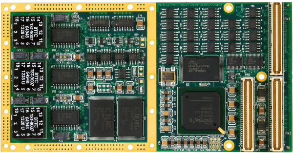
CCPMC-1553B-3Node PMC module is based on ACL's APOORVA IP core and Spartan-6 FPGA.
BC/RT/MT Bus Controller (BC), Remote Terminal (RT) and Monitor Terminal (MT) modes are independently supported on each channel of the PMC-1553B-3Node module.
Introduction
The CCPMC-1553B-3Node provides three dual-redundant MIL-STD-1553B interfaces along with Eight RS-422 channels on a PMC/CCPMC module.It complements ACL's latest generation of PowerPC-750 based SBC with dual PMC/CCPMC sites.The CCPMC-1553B-3Node comes with VxWorks libraries.To provide full testability, the CCPMC-1553B-3 Node is supplied with Built-In-Test (BIT). BIT software routines, which provides diagnostics to give confidence in the sub-system integration.The product is available in standard air-cooled level as well as Conduction Cooled versions.
Salient Technical Features
32-bit/33 MHz PMC card
Three dual redundant BC/RT/MT MIL-STD-1553B interfaces
Transformer coupled interfaces
Supports PCI interrupts
External BC trigger / RT status brought out
Eight RS-422 channels
Current and temparature monitoring
VxWorks Libraries
Available in Air-cooled and Conduction Cooled Versions
BC / RT / MT Operation
Each channel may be independently programmed for BC, RT, or RT/MT mode. This option makes use of the ACL's APOORVA IP core to provide full support for all modes of operation. When used with ACL's APOORVA IP core, 4K words of memory is available for message preparation and double buffering etc.
BC mode includes advanced features such as bulk-data transfers, frame auto-repeat, automatic retries on the same channel or bus switching on alternate channel, programmable gap times etc
RT mode supports all advanced features including single buffering, double buffering, sub-address circular buffering, programmable command illegalisation and Busy etc.
MT modes allows all standard features including word monitoring, selective message monitoring etc
Simultaneous RT / monitor mode is also supported as it is required some times for backup BC terminals.
Hard-warable and Software Programmable RT Addressing
The RT address of each channel on the CCPMC-1553B-3Node may be set by Library functions. RT address is also settable through Hardware settings as per notice-2 features. In this mode the software addressing is disabled.
BC Trigger / RT Status
An external trigger line is provided for each channel to allow hardware control of the BC. Messages may be pre-programmed, and then the BC can start from the point the trigger signal is activated.
In RT mode this line becomes a sub-system status line, used to indicate a failure within the sub-system.
RS-422 Channels
The CCPMC-1553B-3Node module is supported with Eight RS-422 channels. A number of software routines are provided in VxWorks environment, to access and utilize each and every features of on-board serial controller chip.
Software support
ACL provides CCPMC-1553B-3Node with driver and library software for VxWorks operating system environment to assist in software development.
On requirement basis libraries and driver software for other Operating Systems can be provided.
PMC-1553B-1N: Single Node PMC 1553B Module with RS-422
PMC-1553B-2N: Two Node PMC 1553B Module with RS-422
PMC-1553B-3N: Three Node PMC 1553B Module with RS-422
CCPMC Based APOORVA-1553B Four Node BCRTMT Add On Card

The APOORVA-1553B Based BCRTMT is a CCPMC Four Node MIL-STD-1553B interface card which can be hosted by any SBC with PMC sites. The CCPMC card provides up to Four independently configurable buses. Each Bus provides simultaneously dual redundant BC/RT/MT or BC, RT & MT (based on ACL’s APOORVA-1553B Core) concurrently conforming to MIL-STD-1553B Notice-2. The design supports multiple modules on single SBC - limitations being: available system free CCPMC sites and computational power of the Computer. Thus, the APOORVA-CCPMC-FOUR-BCRTMT-1553B is an excellent choice for dynamic real-time avionics simulations. The on-board double buffered dual port memory facilitates parallel message preparation & transfers, increasing the effective throughput.
The APOORVA-1553B Based BCRTMT module comes with Real Time Operating System (RTOS) Bus Libraries, powerful C-callable library routines to access the bus at various levels of abstraction, hardware complexities being transparent to the user. The performance of APOORVA-1553B Based BCRTMT is far superior to solutions offered by others around the globe.
Apoorva provides a unique facility to the user to enable or disable the messages in the Frame.
Up to Four independently configurable buses. Each Bus provides simultaneously dual redundant BC/RT/MT or BC, RT & MT nodes (based on options chosen) conforming to MIL-STD-1553B Notice-2.on one system free CCPMC site.
Supports full MIL-STD-1553B Notice-2.
Supports all 1553B message formats and mode-codes.
On board time-tag counter.
RT Sub-address circular buffers to support bulk data transfers.
Optional separation of RT broadcast data.
Each channel supports double buffered dual ported 7.5 K X 16 bit memory for preparation and transfer.
Programmable RT address.
High performance.
Two on-board timers.
Typical Inter-message gap of 10 micro seconds. Optionally 4.20 micro seconds.
Scalable architecture supporting intra system expandability.
Supports multiple bus simulation on single Computing system.
Ideal for real-time avionics simulation.
Bus Libraries: Powerful C-callable routines to support BC/RT/MT or BC, RT & MT functions.
Powerful message debugging facility.
Unprecedented Flexibility: Minor Frame Time Programmable in steps of 1.0 milli seconds accurately along with Minor frame messages loadable in hardware itself to provide accurate real-time performance.
Built in Diagnostic and test S/W for diagnostics.
Real Time OS Bus Libraries.
| As BC | 7.5 K words | |
| As RT | 7.5 K words | |
| As MT | 16 K words | |
| Circular Buffer | 15 K words |
With the APOORVA-1553B Based BCRTMT module, the following Errors can be injected to verify the LRUs and other systems functioning:
Manchester errors
Bit length errors
Word count errors
Bi-phase errors
Sync errors
Gap time introduction etc.
The APOORVA-1553B Based BCRTMT CCPMC module comes with C-callable library functions/routines to utilise the resources of the module.
APOORVA-CCPMC-ONE-BC, RT & MT-1553B: CCPMC bus based MIL-STD-1553B One Node Module supporting BC, RT & MT (simultaneously).
APOORVA-CCPMC-TWO-BC, RT & MT-1553B: CCPMC bus based MIL-STD-1553B Two Node Module supporting BC, RT & MT (simultaneously) for each bus.
APOORVA-CCPMC-ONE-BC/RT/MT-1553B: CCPMC bus based MIL-STD-1553B One Node BC/RT/MT Module.
APOORVA-CCPMC-TWO-BC/RT/MT-1553B: CCPMC bus based MIL-STD-1553B Two Node BC/RT/MT Module.
APOORVA-CCPMC-THREE-BC, RT & MT-1553B: CCPMC bus based MIL-STD-1553B Three Node Module supporting BC, RT & MT (simultaneously).
APOORVA-CCPMC-FOUR-BC, RT & MT-1553B: CCPMC bus based MIL-STD-1553B Four Node Module supporting BC, RT & MT (simultaneously) for each bus.
APOORVA-CCPMC-THREE-BC/RT/MT-1553B: CCPMC bus based MIL-STD-1553B Three Node BC/RT/MT Module.
APOORVA-CCPMC-FOUR-BC/RT/MT-1553B: CCPMC bus based MIL-STD-1553B Four Node BC/RT/MT Module.
CCPMC Based APOORVA-1553B Four Node MRTBCMT Add On Card
The APOORVA-1553B Based MRTBCMT is a CCPMC Four Node MIL-STD-1553B card and can be hosted by any standard single board computer with CCPMC sites providing simultaneously Four buses each with dual redundant 31RTs, BC & MT (based on ACL’s Apoorva-1553B Core) concurrently conforming to MIL-STD-1553B Notice-2. The design supports a single SBC hosting multiple modules - limitations being: available CCPMC sites and computational power of SBC. Thus, the APOORVA-1553B Based MRTBCMT is an excellent choice for dynamic real-time avionics simulations. The on-board double buffered dual port memory facilitates parallel message preparation & transfers, increasing the effective throughput.
The APOORVA-1553B Based MRTBCMT module comes with Real Time Operating System (RTOS) Bus Libraries, powerful C-callable library routines to access the bus at various levels of abstraction, hardware complexities being transparent to the user. The performance of APOORVA-1553B Based MRTBCMT is far superior to solutions offered by others around the globe.
Apoorva provides a unique facility to the user to enable or disable the messages in the Frame.
Provides simultaneously up to Four buses each with dual redundant 31RTs, BC & MT (based on ACL’s APOORVA-1553B Core) conforming to MIL-STD-1553B Notice-2 on one free CCPMC site.
Supports full MIL-STD-1553B Notice-2.
Supports all 1553B message formats and mode-codes.
On board time-tag counter.
RT Sub-address circular buffers to support bulk data transfers.
Optional separation of RT broadcast data.
Each channel supports double buffered dual ported 7.5 K X 16 bit memory for preparation and transfer.
Programmable RT address.
High performance.
Scalable architecture supporting intra system expandability.
Supports multiple bus simulation on single Computing system.
Ideal for real-time avionics simulation.
Built in test S/W for diagnostics.
Bus Libraries: Powerful C-callable routines to support BC, RT & MT functions.
Powerful message debugging facility.
Unprecedented Flexibility: Minor Frame Time Programmable in steps of 1.0 milli seconds accurately along with Minor frame messages loadable in hardware itself to provide accurate real-time performance.
Typical Inter-message gap of 10 micro seconds.
Real Time OS Bus Libraries.
| As BC | 7.5 K words | |
| As RT | 7.5 K words | |
| As MT | 16 K words | |
| Circular Buffer | 256 K words |
With the APOORVA-1553B Based MRTBCMT module, the following Errors can be injected to verify the LRUs and other systems functioning:
Manchester errors
Bit length errors
Word count errors
Bi-phase errors
Sync errors
Gap time introduction etc.
The APOORVA-CCPMC-MRT-BC-MT-1553B CCPMC bus based module comes with C-callable library functions/routines to utilise the resources of the module.
APOORVA-CCPMC-ONE-MRT-BC-MT-1553B: CCPMC bus based MIL-STD-1553B Simulator / tester Module providing Simultaneous 31RTs, BC & MT on One 1553B bus
APOORVA-CCPMC-TWO-MRT-BC-MT-1553B: CCPMC bus based MIL-STD-1553B Simulator / tester Module providing Simultaneous 31RTs, BC & MT on Two 1553B buses
APOORVA-CCPMC-THREE-MRT-BC-MT-1553B: CCPMC bus based MIL-STD-1553B Simulator / tester Module providing Simultaneous 31RTs, BC & MT on Three 1553B buses
APOORVA-CCPMC-FOUR-MRT-BC-MT-1553B: CCPMC bus based MIL-STD-1553B Simulator / tester Module providing Simultaneous 31RTs, BC & MT on Four 1553B buses
PCMCIA Based APOORVA-1553B Single Node MRTBCMT PCMCIA Card
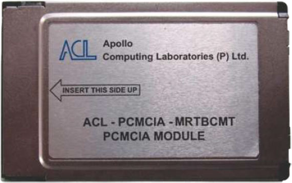
The APOORVA-1553B Based MRTBCMT is a PCMCIA PC Card form factor Type-II (Release 2.10 compatible) MILSTD-1553B module. The Module can be hosted by Note Book Computers (Pentium-III or higher configuration) having Type-II PCMCIA slots, providing simultaneously with dual redundant 31RTs, BC & MT (based on ACL’s Apoorva-1553B Core) nodes conforming to MIL-STD-1553B Notice-2. The design supports a single Note Book Computer/Laptop hosting multiple modules - limitations being: available system free slots and computational power of Note Book PC host. Thus, the APOORVA-1553B Based MRTBCMT is an excellent choice for dynamic real-time avionics simulations. The on-board double buffered dual port memory facilitates parallel message preparation & transfers, increasing the effective throughput.
The APOORVA-1553B Based MRTBCMT comes with Bus Libraries, powerful C-callable library routines to access the bus at various levels of abstraction, hardware complexities being transparent to the user. Higher level functions like data formatting, logging, display etc. The performance of APOORVA-1553B Based MRTBCMT is far superior to solutions offered by others around the globe.
The Module is also provided with Four RS-422 Channels.
PCMCIA Type-II Release 2.10 Compliant.
Provides simultaneously with dual redundant 31RTs, BC & MT (based on ACL’s APOORVA-1553B Core) conforming to MIL-STD-1553B Notice-2 on one Note Book Computer system free PCMCIA slot.
Supports full MIL-STD-1553B Notice-2.
Supports all 1553B message formats and mode-codes.
On board time-tag counter.
RT Sub-address circular buffers to support bulk data transfers.
Optional separation of RT broadcast data.
Each channel supports double buffered dual ported 7.5 K X 16 bit memory for preparation and transfer.
Programmable RT address.
High performance.
Scalable architecture supporting intra system expandability.
Supports multiple bus simulation on single Note Book Computer.
Ideal for real-time avionics simulation.
Built in test S/W for diagnostics.
Bus Libraries: Powerful C-callable routines to support BC, RT & MT functions.
Parmon: Parametric Monitoring Software, a user friendly Menu driven Software is available.
Powerful message debugging facility.
Unprecedented Flexibility: Minor Frame Time Programmable in steps of 1.0 milli seconds accurately along with Minor frame messages loadable in hardware itself to provide accurate real-time performance.
Typical Inter-message gap of 10 micro seconds.
Supported drivers for Windows 2000, Windows XP, Windows 7 and Linux.
Optional : Real Time OS Libraries.
MEMORY
| As BC | 7.5 K words | |
| As RT | 7.5 K words | |
| As MT | 16 K words | |
| Circular Buffer | 256 K words |
With the APOORVA-1553B Based MRTBCMT module, the following Errors can be injected to verify the LRUs and other systems functioning:
Manchester errors
Bit length errors
Word count errors
Bi-phase errors
Sync errors
Gap time introduction etc.
The Apoorva-PCMCIA-MRT-BC-MT-1553B based PCMCIA Bus Based add-on card comes with C-callable library functions/routines to utilise the resources of the card.
APOORVA-PCMCIA-SINGLE-MRT-BC-MT-1553B: PCMCIA bus based MIL-STD-1553B Simulator / tester providing Simultaneous 31RTs, BC & MT on Single 1553B bus along with Four RS-422 Channels
* These variants are also available with ACL. Contact ACL for further details.
PCMCIA Based APOORVA-1553B Single Node BCRTMT PCMCIA Card
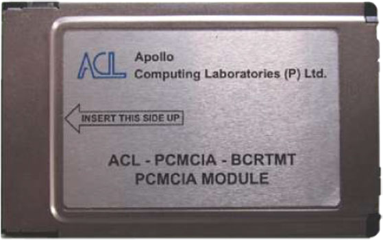
The APOORVA-1553B Based BCRTMT is a PCMCIA PC Card form factor Type-II (Release 2.10 compatible) MIL-STD-1553B module. The Module can be hosted by Note Book Computers (Pentium-III or higher configuration) having Type-II PCMCIA slots, providing simultaneously with dual redundant BC/RT/MT or BC, RT & MT (based on ACL’s Apoorva-1553B Core) nodes conforming to MIL-STD-1553B Notice-2. The design supports a single Note Book Computer/Laptop hosting multiple modules - limitations being: available system free slots and computational power of Note Book PC host. Thus, the APOORVA-1553B Based BCRTMT is an excellent choice for dynamic real-time avionics multiple bus simulations. The on-board double buffered dual port memory facilitates parallel message preparation & transfers, increasing the effective throughput.
The APOORVA-1553B Based BCRTMT Add-on card comes with Bus Libraries, powerful C-callable library routines to access the bus at various levels of abstraction, hardware complexities being transparent to the user. Higherlevel functions like data formatting, logging, display etc. The performance of APOORVA-1553B Based BCRTMT module is far superior to solutions offered by others around the globe.
The Module is also provided with Four RS-422 Channels.
PCMCIA Type-II Release 2.10 Compliant.
Provides simultaneously with dual redundant BC/RT/MT or BC, RT & MT (based on ACL’s APOORVA-1553B Core) on one Note Book Computer system free PCMCIA slot.
Supports full MIL-STD-1553B Notice-2.
Supports all 1553B message formats and mode-codes.
On board time-tag counter.
RT Sub-address circular buffers to support bulk data transfers.
Optional separation of RT broadcast data.
Each channel supports double buffered dual ported 7.5 K X 16 bit memory for preparation and transfer.
Programmable RT address.
High performance.
Scalable architecture supporting intra system expandability.
Supports multiple bus simulation on single Note Book Computer.
Ideal for real-time avionics simulation.
Built in test S/W for diagnostics.
Bus Libraries: Powerful C-callable routines to support BC, RT & MT functions.
Parmon: Parametric Monitoring Software, a user friendly Menu driven Software is available.
Powerful message debugging facility.
Unprecedented Flexibility: Minor Frame Time Programmable in steps of 1.0 milli seconds accurately along with Minor frame messages loadable in hardware itself to provide accurate real-time performance.
Typical Inter-message gap of 10 micro seconds.
Supported drivers for Windows 2000, Windows XP, Windows 7 and Linux.
Optional : Real Time OS Libraries.
MEMORY
| As BC | 7.5 K words | |
| As RT | 7.5 K words | |
| As MT | 16 K words | |
| Circular Buffer | 15 K words |
With the APOORVA-1553B Based BCRTMT module, the following Errors can be injected to verify the LRUs and other systems functioning:
Manchester errors
Bit length errors
Word count errors
Bi-phase errors
Sync errors
Gap time introduction etc.
The Apoorva-PCMCIA-MRT-BC-MT-1553B based PCMCIA Bus Based add-on card comes with C-callable library functions/routines(Library Compatibility: With Windows NT 4.0 and VC++ 6.0) to utilise the resources of the card.
APOORVA-PCMCIA-SINGLE-BC-RT-MT-1553B: PCMCIA bus based MIL-STD-1553B Simulator / tester providing Simultaneous BC, RT & MT on Single 1553B bus along with Four RS-422 Channels
* These variants are also available with ACL. Contact ACL for further details.
PCI Express(PCIe) APOORVA PCIe Based BCRTMT 4 Node Card
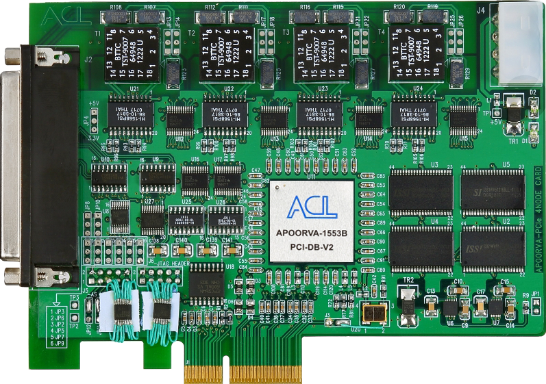
PCIe bus based Apoorva Multi Node MIL-STD-1553B add-on card which can be hosted on any PC (Pentium/i3/i5/i7) PCIe bus interface providing up to Four independently configurable buses. Each Bus provides simultaneously dual redundant BC/RT/MT or BC, RT & MT (based on ACL’s APOORVA-1553B Core)nodes conforming to MIL-STD-1553B Notice-2. The design supports a single PC hosting multiple modules -limitations being: available system free slots and computational power of PC host. Thus, the APOORVA-PCI-FOUR-BCRTMT-1553B is an excellent choice for dynamic real-time avionics simulations. The on-board double buffered dual port memory facilitates parallel message preparation & transfers, increasing the effective throughput.
The APOORVA-1553B Based BCRTMT comes with Bus Libraries, powerful C-callable library routines to access the bus at various levels of abstraction, hardware complexities being transparent to the user. Higher level functions like data formatting, logging, display etc. The performance of APOORVA-1553B Based BCRTMT is far superior to solutions offered by others around the globe.
Apoorva provides a unique facility to the user to enable or disable the messages in the Frame.
Up to Four independently configurable buses. Each Bus provides simultaneously dual redundant BC/RT/MT or BC, RT & MT nodes(based on options chosen) conforming to MILSTD-1553B Notice-2.on PC free PCIe lane x1 slot.
Supports full MIL-STD-1553B Notice-2.
Supports all 1553B message formats and mode-codes.
On board time-tag counter.
RT Sub-address circular buffers to support bulk data transfers.
Optional separation of RT broadcast data.
Each channel supports double buffered dual ported 7.5 K X 16 bit memory for preparation and transfer.
Programmable RT address.
High performance.
Two on-board timers.
Typical Inter-message gap of 10 micro seconds. Optionally 4.20 micro seconds.
Scalable architecture supporting intra system expandability.
Supports multiple bus simulation on single PC.
Ideal for real-time avionics simulation.
Built in test S/W for diagnostics.
Bus Libraries: Powerful C-callable routines to support BC, RT & MT functions.
Unprecedented Flexibility: Minor Frame Time Programmable in steps of 1.0 milli seconds accurately along with Minor frame messages loadable in hardware itself to provide accurate real-time performance.
Parmon: Parametric Monitoring Software, a user friendly Menu driven Software is available.
Powerful message debugging facility.
Supported drivers for Windows 2000, Windows XP, Windows 7 and Linux.
Optional : Real Time OS Libraries.
MEMORY
| As BC | 7.5 K words | |
| As RT | 7.5 K words | |
| As MT | 16 K words | |
| Circular Buffer | 15 K words |
With the APOORVA-1553B Based BCRTMT cards, the following Errors can be injected to verify the LRUs and other systems functioning:
Manchester errors
Bit length errors
Word count errors
Bi-phase errors
Sync errors
Gap time introduction etc.
The APOORVA-1553B Based BCMRTMT PCIe bus based add-on card comes with C-callable library functions/routines to utilize the resources of the card.
APOORVA-PCIe-1553B-Single-BC/RT/MT: PCIe bus based MIL-STD-1553B single node Add-on card supporting BC/ RT/MT.
APOORVA-PCIe-1553B-Two- BC/RT/MT: PCIe bus based MIL-STD-1553B two node Add-on card supporting BC/ RT/ MT.
APOORVA-PCIe-1553B-Three- BC/RT/MT: PCIe bus based MIL-STD-1553B three node Add-on card supporting BC/ RT /MT.
APOORVA-PCIe-1553B-Four- BC/RT/MT: PCIe bus based MIL-STD-1553B four node Add-on card supporting BC/RT/MT.
APOORVA-PCIe-1553B-Single-BC,RT&MT: PCIe bus based MIL-STD-1553B single node Add-on card supporting BC, RT & MT (simultaneously).
APOORVA-PCIe-1553B-Two- BC,RT&MT: PPCIe bus based MIL-STD-1553B two node Add-on card supporting BC, RT & MT (simultaneously).
APOORVA-PCIe-1553B-Three- BC,RT&MT: PCIe bus based MIL-STD-1553B three node Add-on card supporting BC, RT & MT (simultaneously).
APOORVA-PCIe-1553B-Four- BC,RT&MT: PCIe bus based MIL-STD-1553B four node Add-on card supporting BC, RT & MT (simultaneously).
PCI Express(PCIe) APOORVA PCIe Based MRTBCMT 4 Node Card
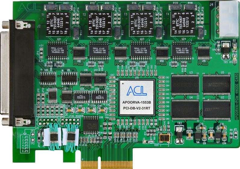
PCIe bus based Apoorva Multi Node MIL-STD-1553B add-on card which can be hosted on any PC (Pentium/i3/i5/i7) PCIe bus interface providing simultaneously Four buses each with dual redundant 31RTs, BC & MT (based on ACL’s Apoorva-1553B Core) nodes conforming to MIL-STD-1553B Notice-2. The design supports a single PC hosting multiple modules - limitations being: available system free slots and computational power of PC host. Thus, the APOORVA-1553B Based MRTBCMT is an excellent choice for dynamic real-time avionics simulations. The on-board double buffered dual port memory facilitates parallel message preparation & transfers, increasing the effective throughput.
The APOORVA-1553B Based MRTBCMT comes with Bus Libraries, powerful C-callable library routines to access the bus at various levels of abstraction, hardware complexities being transparent to the user. Higher level functions like data formatting, logging, display etc. The performance of APOORVA-1553B Based MRTBCMT is far superior to solutions offered by others around the globe.
Apoorva provides a unique facility to the user to enable or disable the messages in the Frame.
Provides simultaneously up to Four buses each with dual redundant 31RTs, BC & MT (based on ACL’s APOORVA-1553B Core) conforming to MIL-STD-1553B Notice-2 on any PC free PCIe slot.
Supports full MIL-STD-1553B Notice-2.
Supports all 1553B message formats and mode-codes.
On board time-tag counter.
RT Sub-address circular buffers to support bulk data transfers.
Optional separation of RT broadcast data.
Each channel supports double buffered dual ported 7.5 K X 16 bit memory for preparation and transfer.
Programmable RT address.
High performance.
Two on-board timers.
Scalable architecture supporting intra system expandability.
Supports multiple bus simulation on single PC.
Ideal for real-time avionics simulation.
Built in test S/W for diagnostics.
Bus Libraries: Powerful C-callable routines to support BC, RT & MT functions.
Parmon: Parametric Monitoring Software, a user friendly Menu driven Software is available.
Powerful message debugging facility.
Unprecedented Flexibility: Minor Frame Time Programmable in steps of 1.0 milli seconds accurately along with Minor frame messages loadable in hardware itself to provide accurate real-time performance.
Supported drivers for Windows 2000, Windows XP, Windows 7 and Linux.
Optional : Real Time OS Libraries.
MEMORY
| As BC | 7.5 K words | |
| As RT | 7.5 K words | |
| As MT | 16 K words | |
| Circular Buffer | 15 K words |
With the APOORVA-1553B Based MRTBCMT cards, the following Errors can be injected to verify the LRUs and other systems functioning:
Manchester errors
Bit length errors
Word count errors
Bi-phase errors
Sync errors
Gap time introduction etc.
The APOORVA-1553B Based MRTBCMT PCIe bus based add-on card comes with C-callable library functions/routines to utilise the resources of the card
APOORVA-PCIe-1553B-Single-BC,MRT&MT : PCIe bus based MIL-STD-1553B Simulator / tester providing Simultaneous 31RTs, BC & MT on one 1553B buses
APOORVA-PCIe-1553B-Two- BC,MRT&MT: PCIe bus based MIL-STD-1553B Simulator / tester providing Simultaneous 31RTs, BC & MT on two 1553B buses
APOORVA-PCIe-1553B-Three- BC,MRT&MT: PCIe bus based MIL-STD-1553B Simulator / tester providing Simultaneous 31RTs, BC & MT on three 1553B buses
APOORVA-PCIe-1553B-Four- BC,MRT&MT: PCIe bus based MIL-STD-1553B Simulator / tester providing Simultaneous 31RTs, BC & MT on four 1553B buses
USB Based Multi Protocol Module
USB Based Multi Protocol Module Providing MIL-STD-1553B, ARINC-429, RS-422/232, AIO & DIO Interfaces
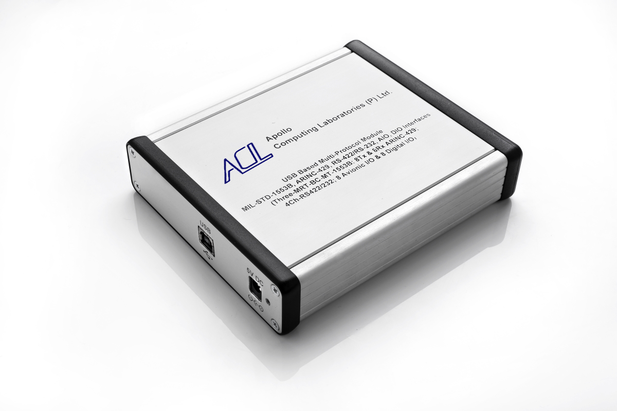
The ACL-USB-APOORVA-Module is a Multi protocol device supporting MIL-STD-1553B Dual Redundant MRTBCMT/BCRTMT up to three buses, ARINC-429 8 Transmit & 8 Receive channels and 4 Nos RS-422 (or) 2 Nos RS-232 & 2 Nos RS-422 can be hosted on any PC / portable computer having USB 2.0 or higher compliant port.
USB interface providing simultaneously three buses each with dual redundant 31RTs/RT, BC & MT (based on ACL’s Apoorva-1553B Core) nodes conforming to MIL-STD-1553B Notice-2. The ACL-USB-APOORVA Based MRTBCMT/BCRTMT is an excellent choice for dynamic real-time avionics simulations. The on-board double buffered dual port memory facilitates parallel message preparation & transfers, increasing the effective throughput.
ARINC 429 Receive channels speed can be set by the user and independent label and SDI filtering. Transmit channels can be independently set for standard low or high speed bit rate (12.5 Kbps or 100 Kbps). Each transmit channel automatically maintains accurate label repetition rates and are capable of driving a full Multiple standard ARINC 429 receiver loads. To support data transfer protocols, a periodic words can be transmitted without altering the timing of periodic words. All channels can be monitored independently or by using a channel/label filter. The ACL PASIT API provides for automatic scheduling of labels based on transmission rates, making it straight-forward to implement transmission schedules from an ICD or migrate from third party products.
The module provides four asynchronous communication channels of baud rates up to 1 Mbps, configurations available in either RS-422(4-ch) or RS-232 (2-ch) & RS-422 (2-ch). The Module complaint with USB 2.0 High speed upto 480 Mbps.
The ACL-USB-APOORVA-Module comes with Bus Libraries, powerful C-callable library routines to access the bus at various levels of abstraction, hardware complexities being transparent to the user. Optionally the module is supported by an user friendly, menu driven, configurable software packages, with higher level functions like data formatting, logging, display etc.
Apoorva-1553B
Provides simultaneously up to Four buses each with dual redundant 31RTs/RT, BC & MT (based on ACL’s APOORVA-1553B Core) conforming to MIL-STD-1553B Notice-2 on ony PC free USB slot.
Supports full MIL-STD-1553B Notice-2.
Supports all 1553B message formats and mode-codes.
On board time-tag counter.
RT Sub-address circular buffers to support bulk data transfers.
Optional separation of RT broadcast data.
Each channel supports double buffered dual ported 7.5 K X 16 bit memory for preparation and transfer.
Programmable RT address.
High performance.
Scalable architecture supporting intra system expandability.
Supports multiple bus simulation on single computing system.
Ideal for real-time avionics simulation.
Built in test S/W for diagnostics.
Bus Libraries: Powerful C-callable routines to support BC, 31RT/RT & MT functions.
Parmon: Parametric Monitoring Software, a user friendly Menu driven Software is available.
Powerful message debugging facility.
Unprecedented Flexibility: Minor Frame Time Programmable in steps of 1.0 milli seconds accurately along with Minor frame messages loadable in hardware itself to provide accurate real-time performance.
Typical Inter-message gap of 10 micro seconds.
Supported drivers for Windows 2000, Windows XP, Windows 7 and Linux.
Optional : Real Time OS Libraries.
MEMORY
| As BC | 7.5 K words | |
| As RT | 7.5 K words | |
| As MT | 16 K words | |
| Circular Buffer | 256 K words |
Apoorva ARINC-429
1) Numeric and file transfer protocols
2) Set parity per channel (odd/even/data)
3) Sync output on all or selected messages
4) Standard and custom bit rates
i) 12.5 Kbps and 100 kbps standard
ii) Configurable per channel
iii) Wide range of custom bit rates
RS-422 /RS-232
1) Baud rates up to 1Mbps
2) Optional configurations RS-422/ RS-232
3) Variable data widths
4) Set parity per channel (odd/even/none)
With The APOORVA-1553B Based MRTBCMT/BCRTMT Module, the following Errors can be injected to verify the LRUs and other systems functioning:
Manchester errors
Bit length errors
Word count errors
Bi-phase errors
Sync errors
Gap time introduction etc.
The APOORVA-1553B Based MRTBCMT/BCRTMT USB based Module comes with C-callable library functions/routines to utilise the resources of the card.
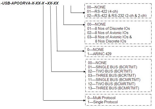
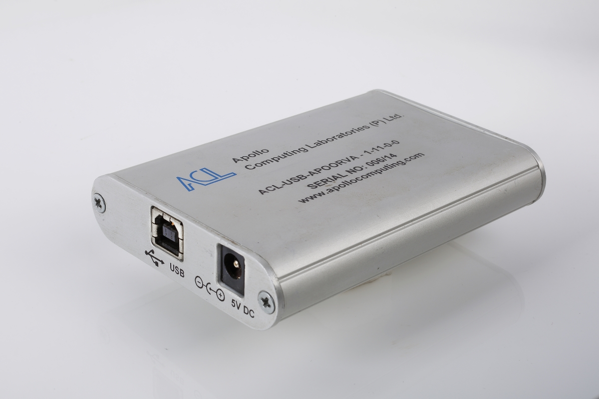
ACL-USB-APOORVA-X-XX-X-XX-XX
EX: FOR 1553B SINGLE BUS MULTIRT’S BCMT PART NO IS ACL-USB-APOORVA-1-11-0-00-00
EX: FOR ARINC 429 PART NO IS ACL-USB-APOORVA-1-00-1-00-00
EX: FOR RS422 & RS232 (2-ch & 2-ch) PART NO IS ACL-USB-APOORVA-1-00-0-00-02
EX: FOR 1553B MULTI PROTOCOL MULTI RT THREE BUS, ARINC 429 PART NO IS ACL-USB-APOORVA-0-13-1-00-00
USB Based Multi Protocol Module
USB Based Multi Protocol Module Providing MIL-STD-1553B,CAN (ARINC-825) Interfaces
The ACL-USB-APOORVA-Module is a Multi protocol device supporting single MIL-STD-1553B Dual Redundant MRTBCMT/BCRTMT, 12 channels of CAN (ARINC-825) interfaces can be hosted on any PC / portable computer having USB 2.0 or higher compliant port.
USB interface providing simultaneously dual redundant 31RTs/RT, BC & MT (based on ACL’s Apoorva-1553B Core) conforming to MIL-STD-1553B Notice-2. The ACL-USB-APOORVA Based MRTBCMT/BCRTMT is an excellent choice for dynamic real-time avionics simulations. The on-board double buffered dual port memory facilitates parallel message preparation & transfers, increasing the effective throughput.
The ACL-USB-1553B/CAN Interface module was designed primarily to support portable applications where MIL-STD-1553B and ARINC 825 have to be handled simultaneously. It supports any portable application and in particular Aircraft Portable Data Loaders which operate in accordance with MIL-STD-1553B and ARINC 825 specifications. Despite the emphasis on Data Loading applications the module’s high performance and feature rich compact design makes it the ideal choice for many other applications. Existing test- and integration infrastructures for one or the other can then be used for both.
The ACL-USB-CAN provides this convenient high speed distributed interfacing capability for accessing 12 CAN 2.0A/B channels. Two different methods are provided for transmitting messages which are designed to simplify various practical interfacing tasks. The Module complaint with USB 2.0 High speed upto 480 Mbps.
The ACL-USB-APOORVA-Module comes with Bus Libraries, powerful C-callable library routines to access the bus at various levels of abstraction, hardware complexities being transparent to the user. Optionally the module is supported by an user friendly, menu driven, configurable software packages, with higher level functions like data formatting, logging, display etc.
Apoorva-1553B
Provides simultaneously dual redundant 31RTs/RT, BC & MT (based on ACL’s APOORVA-1553B Core) conforming to MIL-STD-1553B Notice-2 on ony PC free USB slot.
Supports full MIL-STD-1553B Notice-2.
Supports all 1553B message formats and mode-codes.
On board time-tag counter.
RT Sub-address circular buffers to support bulk data transfers.
Optional separation of RT broadcast data.
Each channel supports double buffered dual ported 7.5 K X 16 bit memory for preparation and transfer.
Programmable RT address.
High performance.
Scalable architecture supporting intra system expandability.
Supports multiple bus simulation on single computing system.
Ideal for real-time avionics simulation.
Built in test S/W for diagnostics.
Bus Libraries: Powerful C-callable routines to support BC, 31RT/RT & MT functions.
Parmon: Parametric Monitoring Software, a user friendly Menu driven Software is available.
Powerful message debugging facility.
Unprecedented Flexibility: Minor Frame Time Programmable in steps of 1.0 milli seconds accurately along with Minor frame messages loadable in hardware itself to provide accurate real-time performance.
Typical Inter-message gap of 10 micro seconds.
Supported drivers for Windows 2000, Windows XP, Windows 7 and Linux.
Optional : Real Time OS Libraries.
MEMORY
| As BC | 7.5 K words | |
| As RT | 7.5 K words | |
| As MT | 16 K words | |
| Circular Buffer | 256 K words |
CAN (ARINC-825):
12 CAN 2.0/ARINC 825 Busses (up to 1 Mb/s)
Queued Transmissions for up to 42 messages
RTR Transmissions
Scheduled Transmissions from 1 ms to 16 sec
32-bit Time Stamping with 1 microsecond resolution
Cyclic buffers for receive data, status and Time Stamps
Automatic data transfer to Host Applications
With The APOORVA-1553B Based MRTBCMT/BCRTMT Module, the following Errors can be injected to verify the LRUs and other systems functioning:
Manchester errors
Bit length errors
Word count errors
Bi-phase errors
Sync errors
Gap time introduction etc.
The APOORVA-1553B Based MRTBCMT/BCRTMT USB based Module comes with C-callable library functions/routines to utilise the resources of the card.
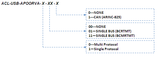
ACL-USB-APOORVA-X-XX-X - X
EX: FOR 1553B SINGLE BUS MULTIRT’S BCMT PART NO IS ACL-USB-APOORVA-1-11-0
EX: FOR CAN (ARINC-825) PART NO IS ACL-USB-APOORVA-1-00-1
EX: FOR 1553B MULTI PROTOCOL MULTI RT Single BUS & CAN (ARINC-825) PART NO IS ACL-USB-APOORVA-0-11-1
MIL-STD-1553B to/from MIL-STD-1773 System
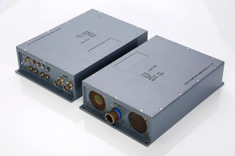
The MIL-STD-1553B to/from Fiber Optic Interface unit provides an interface between the MIL-STD-1553B (electrical bus) and MIL-STD-1773 (Fiber optic bus). The unit provides Fibre optic interface for two channels of MIL-STD-1553B bus. Either two channels of same bus (i.e. dual redundant channels) or single channel of two different buses can be connected to FO.
The unit finds applications requiring long distance data transfers through MIL-STD-1553B protocol involving bus lengths of the order of 1 - 3 kilometres. The unit also can be used for 1773 to MIL-STD-1553B conversions facilitating the testing of optical systems with existing MIL-STD-1553B test equipment. The unit also can be used for Wire to/from Fiber Conversion applications.
The unit facilitates the MIX & Match of MIL-STD-1553B/1773 Buses.
General Features
Provides interface between electrical bus & optical bus.
Fully Compliant to MIL-STD-1553B and MIL-STD-1773.
Bus extender or stub extender for long bus length applications involving 1-3 Kms.
Improved noise immunity than MIL-STD-1553B bus.
Selectable MIL-STD-1553B Transformer coupling (Optionally direct coupling is provided).
Operates with both MIL-STD-1553A and MIL-STD-1553B.
Half duplex with bi-directional data transfers.
Self contained unit.
Data Rate: 1Mbits/sec.
Optical Signal format: Unipolar Manchester-II.
Compatible with MIL-STD-1553B.
Specifications
Input Voltage : 28 ± 2V.
Input Current (Max) : 400 mA.
Power Dissipation (Max) : 11.2 W.
Power Monitoring Status : +28V status (Red), +5V status (Red).
Input Voltage Interface : D38999/20WB35PN (13 Pin Circular Connector).
Bus-A, Bus-B interface : BJ77 (3 Pin Female Connector).
1553B Receiver
Threshold Voltage
Transformer Coupled
Measured on Stub : 0.860Vp-p
Common-Mode Voltage : 10Vpeak
1553B Transmitter
Differential Output Voltage
Direct Coupled across 35 Ohms
Measured on bus : 9 Vp-p
Transformer Coupled across 70 Ohms
Measured on Stub : 27 Vp-p Output
Noise Direct Coupled : 10 mVp-p
Output Noise Transformer Coupled :
250 mVp-p Rise / Fall Time : 300 ns
Fiber Optic Interface : Multimode FC/SC/ST type or Single Mode FC/SC/ST type (as per selected option).
Wavelength Options : Multimode = 1310 nm (as per selected option) Single Mode = 1550 nm (as per selected option).
Fiber Optic Cable Type : 62.5/125nm for Multi mode. 9/125nm for Single mode.
Protection : Reverse voltage protection on input power.
Health Status : SDA (Green), SDB (Green).
Mechanical Dimensions : (220.00 mm x 145.00 mm x 52.00 mm).
Cooling : Forced Air cooling.
Operating Temperature : 0°C to +70°C.
Storage Temperature : -40°C to + 85°C.
Operates from 28V DC power.
Environment Operating Free Air Temperature : 0°C to 50°C.
Relative Humidity : Upto 90% (Non-condensing).
Input / Output Connectors
The BJ-77 connectors are used for MIL-STD-1553B channels
The FC/SC/ST connectors are used for mating with optical cable
ACL- FOIF-1773-MM: MIL-STD-1553B to/from MIL-STD-1773 System with Multi Mode Transceivers with Transformer coupled bus.
ACL- FOIF-1773-SM: MIL-STD-1553B to/from MIL-STD-1773 System with Single Mode Transceivers with Transformer coupled bus.
Note-1: Direct Coupled Bus is available as an optional.
Note-2: ACL is continuously working on improvements of its products; hence these specifications are subject to change without any notice. Wherever the products are updated, the updated/revised version will be supplied.
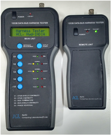
Test Equipments Harness - Tester
The following faults can occur in the harness of 1553B network because of crushed cables, failed connector joints or human errors etc.
Stub / Bus side open.
Stub / Bus side short.
Shorts to shield on the bus and on the stubs.
Phase reversal (swapping of high and low wires resulting in phase change).
Terminators open / improper value terminators.
This Harness Tester will be used to check all the above MIL-STD 1553B network faults. All measurements are of Pass/Fail type with LED indication. Being handheld instrument it is very easy to operate/use this instrument both on the field and off the field also. It has been a common practice to check the equipment hardware and software whenever a problem is found in the 1553B harness to which the RT / LRU’s are connected. Harness Tester is the one which tests and indicates some particular problems found usually in 1553B harness.
Harness Tester also measures Impedance of the Remote Terminal (RT) / LRU.
Detects short & opens in the Stubs of main 1553B Bus from Stub ports.
Detects short to shield in the 1553B Bus and Stubs from the Stub ports.
Detects open, short or incorrect value terminators from the Stub ports.
Detects phase reversal (Swapping of high & low wires resulting in phase change).
Measures Impedance of the LRUs/RT.
ACL-DBHT-000 : ACL 1553B DATA BUS HARNESS TESTER
ACL-DBHT-IMP : ACL 1553B DATA BUS HARNESS TESTER WITH IMPEDANCE MEASUREMENT
Test Equipments RT-Validation Suit
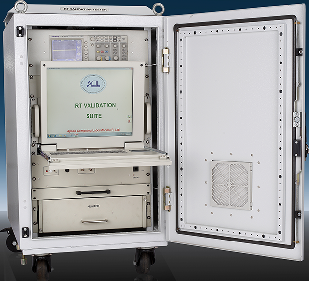
RT Validation Suite can be used to test and clear Remote Terminals of LRUs with respect to MIL-STD-1553B electrical characteristics like amplitude, rise time and fall time, etc. (as given in MIL-STD-1553B product validation plan) before LRUs are installed on Aircraft.
| S.No | Type of Test | ||||||||||||||||||||
|---|---|---|---|---|---|---|---|---|---|---|---|---|---|---|---|---|---|---|---|---|---|
| 1.0 | Functional Tests | ||||||||||||||||||||
| 1.1 | Response To Command Word Test | ||||||||||||||||||||
|
|||||||||||||||||||||
| 1.2 | Inter Message Gap Test | ||||||||||||||||||||
|
|||||||||||||||||||||
| 1.3 | Parity Test | ||||||||||||||||||||
|
|||||||||||||||||||||
| 1.4 | Word Length Test | ||||||||||||||||||||
|
|||||||||||||||||||||
| 1.5 | Bi-Phase Encoding Test | ||||||||||||||||||||
|
|||||||||||||||||||||
| 1.6 | Sync Encoding Test | ||||||||||||||||||||
|
|||||||||||||||||||||
| 1.7 | Message Length Test | ||||||||||||||||||||
|
|||||||||||||||||||||
| 1.8 | Broadcast Message Test | ||||||||||||||||||||
| 1.9 | Contiguous Data Test | ||||||||||||||||||||
| 1.10 | Mode commands Test | ||||||||||||||||||||
|
|||||||||||||||||||||
| 1.11 | Transmit Last Status Test | ||||||||||||||||||||
| 1.12 | Transmit Shut Down Override Test | ||||||||||||||||||||
| 1.13 | Reset Remote Terminal Test | ||||||||||||||||||||
| 1.14 | Error Injection Broadcast Msg Test | ||||||||||||||||||||
| 1.15 | Data Wrap around Test | ||||||||||||||||||||
| 1.16 | Broadcast Mode Command Test | ||||||||||||||||||||
| 2.0 | Electrical Tests O/P Characteristics | ||||||||||||||||||||
| 2.1 | Zero crossing Stability | ||||||||||||||||||||
| 2.2 | Output Symmetry (for 6 samples) | ||||||||||||||||||||
| 2.3 | Distortion/ Overshoot/Ringing | ||||||||||||||||||||
| 2.4 | Amplitude Pk-Pk | ||||||||||||||||||||
| 2.5 | Power on Response | ||||||||||||||||||||
| 2.6 | Rise time and Fall time | ||||||||||||||||||||
| 2.7 | Power on/off Noise | ||||||||||||||||||||
| 2.8 | O/p Isolation | ||||||||||||||||||||
| 2.9 | RT Response Time I/P Characteristics | ||||||||||||||||||||
| 2.10 | Rise time and Fall time | ||||||||||||||||||||
| 2.11 | Amplitude variation | ||||||||||||||||||||
| 2.12 | Noise Rejection | ||||||||||||||||||||
| 2.13 | Common Mode Rejection Test |
RT Validation Suite shall be used for validating the 1553B Remote Terminal’s Electrical characteristics, Functional characteristics (protocol tests) and noise rejection tests.
The RT Validation Suite shall implement all the external interfaces of 1553B RT Module by emulating the Bus controller, Bus Monitor Functions. Measuring instruments shall be connected to the RT module/1553B bus in automated manner through the software control.
The following electrical/Functional characteristics can be monitored using the RT Validation Suite.
A) Electrical characteristics:
i) Output
1) Zero crossing Stability
2) Output Symmetry (for 6 samples)
3) Distortion/ Overshoot/Ringing
4) Amplitude Pk-Pk
5) Power on Response
6) Rise time and Fall time
7) Power on/off Noise
8) O/p Isolation
9) RT Response Time
ii) Input
1) Rise time and Fall time
2) Amplitude variation
3) Noise Rejection
4) Common Mode Rejection Test
B) Functional characteristics (Protocol Tests):
1) Response to command Word
2) Inter Message Gap
3) Error Injection
4) Word Length
5) Bi-phase Encoding
6) Sync Encoding
7) Message Length
8) Contiguous Data
9) Terminal Fail Safe
10) Superseding Commands
11) Mode Commands
12) Bus Switching
13) Unique Address
14) RT-RT Broadcast Test
15) Error Injection Broadcast Msg Test
16) Data Wrap around Test
17) Broadcast Mode Command Test
C) Noise Rejection tests
Noise rejection of the RT module will be tested by injecting the noise of 200mv pk-pk (1MHz).
RT VALIDATION SUITE BLOCK DIAGRAM

MODULES OF THE RT VALIDATION SUITE
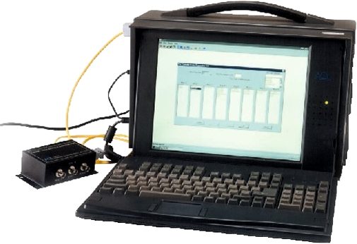
i) Industrial Computer
This PC is configured as BUS controller to schedule the messages to Remote Terminal as well as the Monitor Terminal to monitor the results. It is equipped with single node 1553B add on card .Graphical User Interface software is developed to the switching of the equipments to connect with the 1553B bus. This PC will be using its serial port to communicate with the Switching block.
ii) Switching Block (Xilinx CPLD Based RS232-Switching card)
This is based on XCR Series Xilinx CPLD. Operating voltage of the board is 5V.Board consists of DPDT Latch relays to switch between the inputs and outputs. These relays will be controlled from the I/O Lines of CPLD which are Configured as Outputs. Board communicates to the HOST system through the serial interface over the RS232 line where as the UART Core is emulated in CPLD. The RS-232 interface standard is provided with the help of MAX3221 chip. The card has an extensive reset circuit facility for resetting the all the Relays sequentially there by reducing the surge of current at Power ON. After Power ON the relays can be reset through S/W commands.
iii) Noise Injection Module
This is developed on the PCI Card which is plugged in to the host system.Output of the module is interfaced to the switching Card.This generates a sinusoidal waveform of 1MHz frequency and the amplitude variable from 250mv Pk-Pk to 1.2V Pk-Pk.
iv) PCI Based single node 1553B add on card
This card will be installed in the Industrial PC and works as a BUS Controller as well as the Monitor Terminal. A digital potentiometer is incorporated on the card to vary the 1553B signal’s Amplitude level. This can be controlled through the software interface.
v) Impedance Analyzer Module
This will be used to measure the input impedance of the 1553B bus. This Module is developed on the PCI add on card which is plugged in the host system.Host system S/W can capture the results directly from the module.
vi) Digital Storage Oscilloscope
This will be used to measure Amplitude (Vp-p), Rise Time, Fall Time, Zero Crossing Stability and output symmetry of the 1553B’s signal. This instrument can be interfaced to the Industrial PC though the USB interface to capture the results.
vii) USB/RS232 Converter
This Converter cable is used to interface the switching card to Host PC. It supplies 5V DC to the switching card from USB Power.
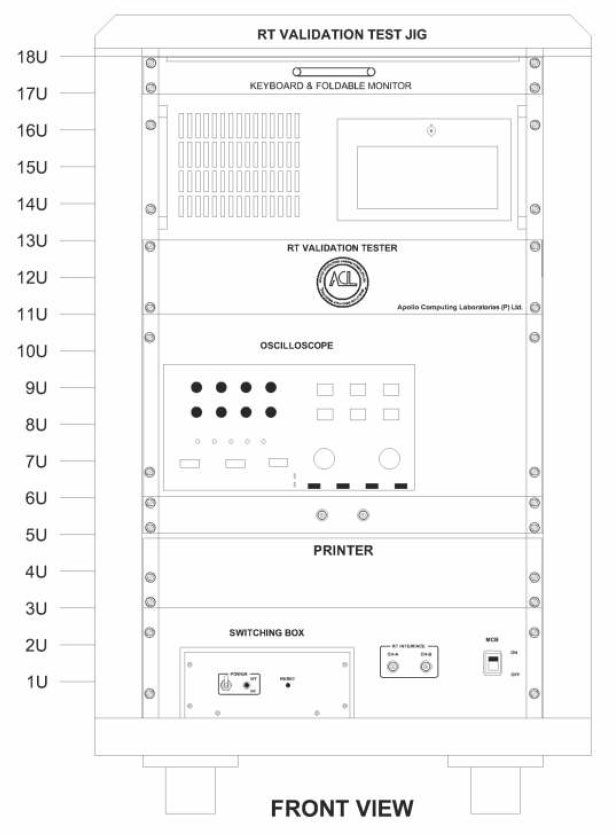
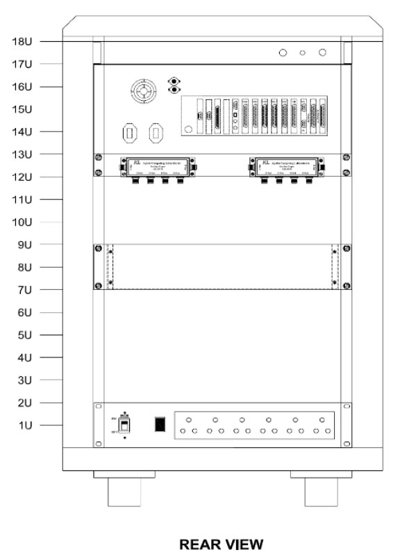
viii) Mounting Rack for total setup Mounting Box for switching Block
A Rack is provided to incorporate all the equipments Industrial PC, Oscilloscope, Impedance Analyzer Switching Block. Switching Card is housed in a mounting box and this box is mounted on the rack.
RT VALIDATION SUITE STRUCTURAL VIEW
RT Validation Suite structural view of front view and rear view as given in below
ACL-RT-VAL: MIL-STD-1553B Based RT Validation Suite.
* ACL is continuously working on improvements of its products; hence these specifications are subject to change without any notice. Wherever the products are updated, the updated/revised version will be supplied.
Test Equipments Avionics Test System (AVTS)
Introduction
The generic configuration of Avionics Testing System (AvTS). The AvTS System consists of Portable Computer along with PCI module supporting MIL-STD-1553B (simultaneously providing BC, 31RTs & MT) and four RS-422 Channels. The BC, RTs and MT related data scheduling and data capture, processing, display and analysis software makes the Avionics systems integration easy.
The software is user friendly and can be easily operated by a person having working experience with MILSTD-1553B systems. The following are the main functions supported by AvTS.
BC Scheduler Software: Schedules the messages for each minor frame.
Monitor Software: Monitors the activities on the bus.
RT Simulation Software: Simulates all the Remote Terminals (31RTs).
RT Validation Software : Provides the standard RT validation test routines
Hardware- General
The Avionics Test System (AvTS) is a Portable Computer based System.
The capacity of storage space is approximately morethan 100GB to accommodate the recording of MIL-STD-1553B bus data and four RS-422 channels data continuously for at least 10 hours .
The Hardware configuration of the system is as follows:
Portable LCD based system with morethan 4 PCI Slots.
Pentium/i3/i5/i7 with minimum 2 GB RAM, minimum 256 GB HDD, minimum 2 USB Ports, 1 Ethernet port and optional 2 Serial Ports & 1 Parallel Port.
High impact fire proof sturdy ABS plastic case with built-in metal chassis.
Adjustable screen for view angle.
13.3” TFT colour LCD screen with 1024 x 768 pixels resolution with adjustable Brightness and Contrast control.
Power supply: Approximately 100 watts, 170 Vac~ 265 Vac, 47 Hz ~ 63 Hz.
Keyboard: Detachable 103 key standard size keyboard with 12 function keys and numeric keypad.
PCI Bus Based Add-on card supporting MIL-STD-1553B Simulator / Tester Providing Simultaneous 31RTs, BC & MT. Optionally the system can provide Two Bus architecture. The card uses MIL/Industrial grade components only.
Bus controller capability conforming to MIL-STD-1553B (Notice-2) with inter message gap of 10 micro sec (typical), Remote terminals up to 31RTs simultaneously conforming to MIL-STD-1553B (Notice-2) along with Monitor Terminal conforming to MIL-STD-1553B (Notice-2).
Supports connection to additional External VGA monitor.
Highly portable: You can pack & start carrying in less than 10 Seconds. Provided with carrying bag.
MIL-STD-1553B Bus and RS-422 PCI MODULE
The AvTS system consists of a PCI card supporting simultaneously BC, 31RTs & MT (Channel-A and Channel-B) for simulating Bus controller (BC), 31 Remote Terminals (RTs) and for monitoring the MIL-STD-1553B bus data (MT) along with 4 RS-422 channels.
CONNECTORS
The AvTS system supports BJ-77 connector Box or two PL-75 or Raychem typeconnectors to connector it with external MIL-STD-1553B data bus.Also the AvTS provides RS-422 connectors to monitor / utilise the RS-422 channels.
SOFTWARE GENERAL
The software is windows based menu driven type. The main menu looks like
| BC/RT/MT | RS-422 | DATABASE | RUN | QUIT |
Optional: A database of Engineering parameters can be generated from ICD supplied in CD/DVD in ORACLE database and to be loaded accordingly. The database will be loaded on default whenever theSoftware is executed.Provision to update the database whenever there is a change in ICD exists inthe Software. The provision to update the database is on selection of DATABASE menu as shownabove.
Bus Controller can initiate transaction just like Mission Computer of Avionics System. It generates messages according to a definable scheduler.
The scheduler is compatible to Mission Computer scheduler.
The BC Scheduler has the following features.
Provision to create 600 messages with Message names as given in Avionics Interface Control Document, of following types which can be added freely in any minor frame
BC to RT Transfers
RT to BC Transfers
RT to RT Transfers
Broadcast Type Transfers
Mode Codes as per Notice-II of MIL-STD-1553B standard.
Maximum length of Message name is equal to 20 characters.
Provision to store data to be transmitted in that particular message in hexadecimal and engineering values.
Provision to change the data while BC is scheduling the messages.
Provision for sending the data stored in a table for that particular message. This will cater to create dynamic changing of data from BC side for that message. It is possible To read a file and store the data in selected message.This will help to reduce the work involved in keying in the data. This will also assist in scheduling the data captured though Bus Monitor.
Create Scheduler, which consists of major cycles of duration 160 mSec.
Each major cycle consists of 8 minor cycles of duration 20 mSec.
Provision to change the duration of major cycle- and minor cycle in steps of 1 mSec.
Provision to change the No. of minor cycles per major cycle from 1 to 32.
Provision to load a file on default whenever the software is executed.
Provision to save scheduler in any drive/directory and load it from any drive / directory.
Provision to RUN the BC for definite number of major cycles, definite amount of time (Ex: 5 minutes etc.) or indefinitely.
Provision to display the No. of major cycles and minor cycles run / amount of time elapsed while running as BC.
Remote Terminal will be able to transact data with BC and any other subsystem as commanded by BC.
Capable of emulating up to 31 Remote Terminals simultaneously at a time.
Valid value of Remote Terminal address is from 1 to 30.
RT selection is by entering RT address. Also RT can be selected using names it self.
Capable of looping back the data (Loop Test). Time broadcast data is sent by BC to all RTs to receive on Sub address 29. The second word of that data is to be sent back in Loop back and MSW message (Transmit sub address 4).
Provision to set bits in status word is provided (Ex: Busy Bit, Service request bit). The setting of bits for 1 major cycle or continuously or for few major cycles is provided.
The data sent by an RT is stored in tables. The data to be sent is keyed in engineering values. For each sub address it is possible to store data, which will be transmitted by RT for every major cycle on BC command, which will assist in creating dynamic data transmission. It is also be possible to read a file and store the data in selected sub address and particular word. This will help to reduce the work involved in keying in the data. This will also assist to input the data captured though Bus Monitor.
When an RT is configured and running the RT number and name will be displayed on run screen.
RT VALIDATION SOFTWARE
Provides RT Validation Tests that are feasible with S/W programming.
The following tests can be done with PASIT:
Valid address test.
Invalid address test.
Word count test.
Sub-address test.
Dual redundant operation.
Mode command tests:
Synchronize without data word, Transmit status, Transmit last command, Dual redundant Transmitter Shutdown & override
Status word tests: Service request, Broadcast, Subsystem flag, Busy flag.
Broadcast messages tests:.
BC-RT broadcast command Broadcast synchronize without data word
Broadcast synchronize with data word
Broadcast transmitter shutdown and override
RT-RT broadcast command
RT-RT transfer tests:.
RT-RT transmit
RT-RT receive
With The AvTS, the following Errors can be injected to verify the LRUs and other systems functioning:
Manchester errors.
Bit length errors.
Word count errors.
Bi-phase errors.
Sync errors.
Gap time introduction etc.
Bus Monitor will capture data transaction on the bus.
The bus monitor can capture all data in Normal format and in Engineering value format (upto 20 parameters will be supported).
Provision for selecting required RT address and SUB address to be monitored is possible. It is possible to select RT by name.
Provision to capture the data for 2 hours with full bus traffic is provided, with all RTs, Sub address and words are selected for monitoring.
It is possible to select and display upto 20 Engineering parameters pertaining to any of the RTs during online monitoring. The parameters are to be selected from the database as described under general requirement of software.
Provision to store the data is provided while monitoring the data online. A text ‘Save Data’ with check box is provided to facilitate starting of saving data. When the check box is selected the PASIT will start storing the data. When the check box is deselected it will stop recording. A dialogue with provision to enter file name is provided. If a file already exists with the filename entered warning message will be posted on the screen.
The provision to display graph of any parameter selected for online monitoring versus Major cycle No. is available. It is also be possible to display 4 graphs together for 4 Engineering parameters during online monitoring.
The captured messages will be displayed with message names and engineering values.
It will be possible to print the captured data to printer/file. Provision to print selected range of messages / range of pages also provided.
It will be possible to filter the captured data in following methods
| Filtering method | Example |
|---|---|
| Range of RTs | RT No.3 to RT No.6 |
| Selected RTs | RT Nos. 6, 11, 15 |
| RT and Subaddress | RT 5 Subaddress 1 |
| Message Names | HEEMl_10l |
| Data Word search for RT and Subaddress | 8000 |
Note:
1) Provision to include sync and broadcast messages is provided while filtering the data. Enable / Disable option is also provided.
2) Logical AND of 2 or 3 of the above filtering condition is also provided .
RS-422 Data Monitoring (Optional)
Screen for displaying RS-422 parameters is provided.
Monitoring of MIL-STD-1553B data along with RS-422 data simultaneously is supported. On toggling the windows the screen will switch between MIL-STD-1553B bus screen and RS-422 screen.
It will be possible to save the monitored RS-422 data for offline analysis.
Offline Analysis of Monitored data
It is possible to replay the recorded MIL-STD-1553B bus data on a personal computer / AvTS.
Software facilitates for free running replay of the data with values of parameters displayed in Engineering units for upto 30 parameters selected from database.
The replay consists of provision to display the graph of a selectedparameter against time on selection.
Provision also exists for replaying RS-422 data also (optional).
DELIVERBLES
The H/W as per the specification.
AvTS Software (Executable) CD.
User Manual.
Acceptance Test Procedure document.
Note-1: Avionics Database entry Software package, which facilitates easy entry, querying, updating, debugging and maintenance of ICDs (Interface Control Documents), is available as an option. Please contact ACL for further details.
Note-2: The PASIT-Software is extensively validated by Aeronautical Development Agency (ADA) and other organisations. The PASIT-Software is under field usage by a major Avionics programme (LCA), in addition to being used by over 30 strategic MIL-STD-1553B users.
ACL-AvTS-SINGLE : Avionics Testing System with single dual redundant MIL-STD-1553B Bus providing BC, 31 RTs simultaneously and MT *
ACL-AvTS-DUAL : Avionics Testing System with two dual redundant MIL-STD-1553B Buses, providing BC, 31 RTs simultaneously and MT on each Bus *
* The optional items are not included in the standard ordering. Hence optional items have to be ordered separately. ACL is continuously working on improvements of its products; hence these specifications are subject to change without any notice. Wherever the products are updated, the updated/revised version will be supplied.
Test Equipments Portable Avionics System Integration Tool (PASIT)
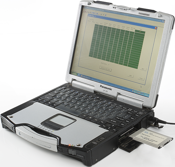
Introduction
The generic configuration of Portable Avionics System Integration Tool (PASIT). The PASIT consist of Notebook Computer along with PCMCIA Type-II module supporting MIL-STD-1553B(simultaneously providing BC, 31RTs & MT) and four RS-422 Channels. The BC, RTs and MT related data scheduling and data capture, processing, display and analysis software makes integration of Avionics Systems easy.
The software is user friendly and can be easily operated by a person having working experience with MILSTD-1553B systems. The following are the main functions supported by PASIT.
BC Scheduler Software: Schedules the messages for each minor frame.
Monitor Software: Monitors the activities on the bus.
RT Simulation Software: Simulates all the Remote Terminals (31RTs) simultaneously.
RT Validation Software : Provides the standard RT validation test routines
Hardware- General
The PASIT is a portable and laptop computer based system.
It contains CD R/W drive to transfer data from hard disk to CD for replaying the data on other computer / PASIT system. The capacity of storage space is approximately 20GB to accommodate the recording of MIL-STD-1553B bus data and four RS-422 channels data continuously for at least 2 hours.
The Hardware configuration of the system:
Mobile Intel® Pentium/i3/i5/i7 Processor.
1GB or Higher DDR RAM standard.
256 GB or Higher Hard Disk.
24X DVD/CDRW Combo Drive.
2-USB (Universal Serial Bus) 2.0 Compliant connectors.
RJ-45 connector for 10/100 Ethernet LAN.
35.8cm XGA TFT display: 1024 x 768 Pixels.
PCMCIA Type-II module tester / simulator supporting BC, 31RTs & MT simultaneously along with 4 RS-422 channels.
MIL-STD-1553B Bus and RS-422 PCMCIA MODULE
The PASIT consists of a PCMCIA card supporting simultaneously BC, 31RTs & MT (Channel-A and Channel-B) for simulating Bus controller (BC), 31 Remote Terminals (RTs) and for monitoring the MIL-STD-1553B bus data (MT) along with Four RS-422 channels.
CONNECTORS
The PASIT system provides two PL-75 or Raychem type connectors to connect it with external MIL-STD-1553B data bus.Also the PASIT provides RS-422 connectors to monitor / utilise the RS-422 channels.
SOFTWARE GENERAL
The software is windows based menu driven type. The main menu looks like:
| BC/RT/MT | RS-422 | DATABASE | RUN | QUIT |
Optional: AA database of Engineering parameters can be generated from ICD supplied in CD/DVD in ORACLE database and to be loaded accordingly. The database will be loaded on default whenever the Software is executed. Provision to update the database whenever there is a change in ICD exists in the Software. The provision to update the database is on selection of DATABASE menu as shown above.
Bus Controller can initiate transaction just like Mission Computer of Avionics System. It generates messages according to a definable scheduler. The scheduler is compatible to Mission Computer scheduler. The BC Scheduler has the following features.
Provision to create 600 messages with Message names as given in Avionics Interface Control Document, of following types which can be added freely in any minor frame
BC to RT Transfers
RT to BC Transfers
RT to RT Transfers
Broadcast Type Transfers
Mode Codes as per Notice-II of MIL-STD-1553B standard.
Maximum length of Message name is equal to 20 characters.
Provision to store data to be transmitted in that particular message in hexadecimal and engineering values.
Provision to change the data while BC is scheduling the messages.
Provision for sending the data stored in a table for that particular message. This will cater to create dynamic changing of data from BC side for that message. It is possible To read a file and store the data in selected message.This will help to reduce the work involved in keying in the data. This will also assist in scheduling the data captured though Bus Monitor.
Create Scheduler, which consists of major cycles of duration 160 mSec.
Each major cycle consists of 8 minor cycles of duration 20 mSec.
Provision to change the duration of major cycle- and minor cycle in steps of 1 mSec.
Provision to change the No. of minor cycles per major cycle from 1 to 32.
Provision to load a file on default whenever the software is executed.
Provision to add messages in minor frame with programmable inter message gap in steps of 1μsec.
Provision to save scheduler in any drive/directory and load it from any drive / directory.
Provision to RUN the BC for definite number of major cycles, definite amount of time (Ex: 5 minutes etc.) or indefinitely.
Provision to display the No. of major cycles and minor cycles run / amount of time elapsed while running as BC.
Remote Terminal will be able to transact data with BC and any other subsystem as commanded by BC.
Capable of emulating up to 31 Remote Terminals simultaneously at a time.
Valid value of Remote Terminal address is from 1 to 30.
RT selection is by entering RT address. Also RT can be selected using names it self.
Capable of looping back the data (Loop Test). Time broadcast data is sent by BC to all RTs to receive on Sub address 29. The second word of that data is to be sent back in Loop back and MSW message (Transmit sub address 4).
Provision to set bits in status word is provided (Ex: Busy Bit, Service request bit). The setting of bits for 1 major cycle or continuously or for few major cycles is provided.
The data sent by an RT is stored in tables. The data to be sent is keyed in engineering values. For each sub address it is possible to store data, which will be transmitted by RT for every major cycle on BC command, which will assist in creating dynamic data transmission. It is also be possible to read a file and store the data in selected sub address and particular word. This will help to reduce the work involved in keying in the data. This will also assist to input the data captured though Bus Monitor.
When an RT is configured and running the RT number and name will be displayed on run screen.
RT VALIDATION SOFTWARE
Provides RT Validation Tests that are feasible with S/W programming.
The following tests can be done with PASIT:
Valid address test.
Invalid address test.
Word count test.
Sub-address test.
Dual redundant operation.
Mode command tests: Synchronize without data word, Transmit status, Transmit last command, Dual redundant Transmitter Shutdown & override.
Status word tests: Service request, Broadcast, Subsystem flag, Busy flag.
Broadcast messages tests:
BC-RT broadcast command Broadcast synchronize without data word
Broadcast synchronize with data word
Broadcast transmitter shutdown and override
RT-RT broadcast command
RT-RT transfer tests:
RT-RT transmit
RT-RT receive
With The PASIT, the following Errors can be injected to verify the LRUs and other systems functioning:
Manchester errors
Bit length errors
Word count errors
Bi-phase errors
Sync errors
Gap time introduction etc.
Bus Monitor will capture data transaction on the bus.
The bus monitor can capture all data in Normal format and in Engineering value format (upto 20 parameters will be supported).
Provision for selecting required RT address and SUB address to be monitored is possible. It is possible to select RT by name.
Provision to capture the data for 2 hours with full bus traffic is provided, with all RTs, Sub address and words are selected for monitoring.
It is possible to select and display upto 20 Engineering parameters pertaining to any of the RTs during online monitoring. The parameters are to be selected from the database as described under general requirement of software.
Provision to store the data is provided while monitoring the data online. A text ‘Save Data’ with check box is provided to facilitate starting of saving data. When the check box is selected the PASIT will start storing the data. When the check box is deselected it will stop recording. A dialogue with provision to enter file name is provided. If a file already exists with the filename entered warning message will be posted on the screen.
The provision to display graph of any parameter selected for online monitoring versus Major cycle No. is available. It is also be possible to display 4 graphs together for 4 Engineering parameters during online monitoring.
The captured messages will be displayed with message names and engineering values.
It will be possible to print the captured data to printer/file. Provision to print selected range of messages / range of pages also provided.
It will be possible to filter the captured data in following methods.
It will be possible to filter the captured data in following methods
| Filtering method | Example |
|---|---|
| Range of RTs | RT No.3 to RT No.6 |
| Selected RTs | RT Nos. 6, 11, 15 |
| RT and Subaddress | RT 5 Subaddress 1 |
| Message Names | HEEMl_10l |
| Data Word search for RT and Subaddress | 8000 |
Note:
1) Provision to include sync and broadcast messages is provided while filtering the data. Enable / Disable option is also provided.
2) Logical AND of 2 or 3 of the above filtering condition is also provided .
RS-422 Data Monitoring (Optional)
Screen for displaying RS-422 parameters is provided.
Monitoring of MIL-STD-1553B data along with RS-422 data simultaneously is supported. On toggling the windows the screen will switch between MIL-STD-1553B bus screen and RS-422 screen.
It will be possible to save the monitored RS-422 data for offline analysis.
Offline Analysis of Monitored data
It is possible to replay the recorded MIL-STD-1553B bus data on a personal computer / AvTS.
Software facilitates for free running replay of the data with values of parameters displayed in Engineering units for upto 30 parameters selected from database.
The replay consists of provision to display the graph of a selectedparameter against time on selection.
Provision also exists for replaying RS-422 data also (optional).
DELIVERBLES
The H/W as per the specification.
PASIT Software (Executable) CD.
User Manual.
Acceptance Test Procedure document.
Note-1: Avionics Database entry Software package, which facilitates easy entry, querying, updating, debugging and maintenance of ICDs (Interface Control Documents), is available as an option. Please contact ACL for further details.
Note-2: The PASIT-Software is extensively validated by Aeronautical Development Agency (ADA) and other organisations. The PASIT-Software is under field usage by a major Avionics programme (LCA), in addition to being used by over 30 strategic MIL-STD-1553B users.
Ordering Information
ACL-PASIT-SINGLE : PASIT with Single Dual redundant MIL-STD-1553B Bus providing BC, 31 RTs simultaneously and MT * along with 4 RS-422 Channels.
* The optional items are not included in the standard ordering. Hence optional items have to be ordered separately. ACL is continuously working on improvements of its products; hence these specifications are subject to change without any notice. Wherever the products are updated, the updated/revised version will be supplied.
Test Equipments Parametric Monitoring Software for APOORVA PCI-1553B & BISA-PCI-1553B cards
Introduction
The PARMON (Parametric Monitor) Software is user friendly and can be easily operated by a person having working experience with MIL-STD-1553B systems. The following are the main functions supported by PARMON.
BC Scheduler Software: Schedules the messages for each minor frame.
Monitor Software: Monitors the activities on the bus.
RT Simulation Software: Simulates all the Remote Terminals (31RTs) simultaneously.
RT Validation Software : Provides the standard RT validation test routines
SOFTWARE - GENERAL
TThe PARMON software is windows based menu driven type. The main menu looks like:
| BC/RT/MT | RS-422 | DATABASE | RUN | QUIT |
Optional: AA database of Engineering parameters can be generated from ICD supplied in CD/DVD in ORACLE database and to be loaded accordingly. The database will be loaded on default whenever the Software is executed. Provision to update the database whenever there is a change in ICD exists in the Software. The provision to update the database is on selection of DATABASE menu as shown above.
Bus Controller can initiate transaction just like Mission Computer of Avionics System. It generates messages according to a definable scheduler. The scheduler is compatible to Mission Computer scheduler. The BC Scheduler has the following features.
Provision to create 600 messages with Message names as given in Avionics Interface Control Document, of following types which can be added freely in any minor frame.
BC to RT Transfers
RT to BC Transfers
RT to RT Transfers
Broadcast Type Transfers
Mode Codes as per Notice-II of MIL-STD-1553B standard.
Maximum length of Message name is equal to 20 characters.
Provision to store data to be transmitted in that particular message in hexadecimal and engineering values.
Provision to change the data while BC is scheduling the messages.
Provision for sending the data stored in a table for that particular message. This will cater to create dynamic changing of data from BC side for that message. It is possible To read a file and store the data in selected message.This will help to reduce the work involved in keying in the data. This will also assist in scheduling the data captured though Bus Monitor.
Create Scheduler, which consists of major cycles of duration 160 mSec.
Each major cycle consists of 8 minor cycles of duration 20 mSec.
Provision to change the duration of major cycle- and minor cycle in steps of 1 mSec.
Provision to change the No. of minor cycles per major cycle from 1 to 32.
Provision to load a file on default whenever the software is executed.
Provision to add messages in minor frame with programmable inter message gap in steps of 1μsec.
Provision to save scheduler in any drive/directory and load it from any drive / directory.
Provision to RUN the BC for definite number of major cycles, definite amount of time (Ex: 5 minutes etc.) or indefinitely.
Provision to display the No. of major cycles and minor cycles run / amount of time elapsed while running as BC.
Remote Terminal will be able to transact data with BC and any other subsystem as commanded by BC.
Capable of emulating up to 31 Remote Terminals simultaneously at a time.
Valid value of Remote Terminal address is from 1 to 30.
RT selection is by entering RT address. Also RT can be selected using names it self.
Capable of looping back the data (Loop Test). Time broadcast data is sent by BC to all RTs to receive on Sub address 29. The second word of that data is to be sent back in Loop back and MSW message (Transmit sub address 4).
Provision to set bits in status word is provided (Ex: Busy Bit, Service request bit). The setting of bits for 1 major cycle or continuously or for few major cycles is provided.
The data sent by an RT is stored in tables. The data to be sent is keyed in engineering values. For each sub address it is possible to store data, which will be transmitted by RT for every major cycle on BC command, which will assist in creating dynamic data transmission. It is also be possible to read a file and store the data in selected sub address and particular word. This will help to reduce the work involved in keying in the data. This will also assist to input the data captured though Bus Monitor.
When an RT is configured and running the RT number and name will be displayed on run screen.
RT VALIDATION SOFTWARE
Provides RT Validation Tests that are feasible with S/W programming.
The following tests can be done with PARMON:
Valid address test.
Invalid address test.
Word count test.
Sub-address test.
Dual redundant operation.
Mode command tests: Synchronize without data word, Transmit status, Transmit last command, Dual redundant Transmitter Shutdown & override.
Status word tests: Service request, Broadcast, Subsystem flag, Busy flag.
Broadcast messages tests:
BC-RT broadcast command Broadcast synchronize without data word
Broadcast synchronize with data word
Broadcast transmitter shutdown and override
RT-RT broadcast command
RT-RT transfer tests:.
RT-RT transmit
RT-RT receive
With the PARMON, the following Errors can be injected to verify the LRUs and other systems functioning:
Manchester errors
Bit length errors
Word count errors
Bi-phase errors
Sync errors
Gap time introduction etc.
Bus Monitor will capture data transaction on the bus.
The bus monitor can capture all data in Normal format and in Engineering value format (upto 20 parameters will be supported).
Provision for selecting required RT address and SUB address to be monitored is possible. It is possible to select RT by name.
Provision to capture the data for 2 hours with full bus traffic is provided, with all RTs, Sub address and words are selected for monitoring.
It is possible to select and display upto 20 Engineering parameters pertaining to any of the RTs during online monitoring. The parameters are to be selected from the database as described under general requirement of software.
Provision to store the data is provided while monitoring the data online. A text ‘Save Data’ with check box is provided to facilitate starting of saving data. When the check box is selected the PASIT will start storing the data. When the check box is deselected it will stop recording. A dialogue with provision to enter file name is provided. If a file already exists with the filename entered warning message will be posted on the screen.
The provision to display graph of any parameter selected for online monitoring versus Major cycle No. is available. It is also be possible to display 4 graphs together for 4 Engineering parameters during online monitoring.
The captured messages will be displayed with message names and engineering values.
It will be possible to print the captured data to printer/file. Provision to print selected range of messages / range of pages also provided.
It will be possible to filter the captured data in following methods.
It will be possible to filter the captured data in following methods
| Filtering method | Example |
|---|---|
| Range of RTs | RT No.3 to RT No.6 |
| Selected RTs | RT Nos. 6, 11, 15 |
| RT and Subaddress | RT 5 Subaddress 1 |
| Message Names | HEEMl_10l |
| Data Word search for RT and Subaddress | 8000 |
Note:
1) Provision to include sync and broadcast messages is provided while filtering the data. Enable / Disable option is also provided.
2) Logical AND of 2 or 3 of the above filtering condition is also provided .
Offline Analysis of Monitored data
It is possible to replay the recorded MIL-STD-1553B bus data on a personal computer / PARMON.
Software facilitates for free running replay of the data with values of parameters displayed in Engineering units for upto 20 parameters selected from database.
The replay consists of provision to display the graph of a selectedparameter against time on selection.
Provision also exists for replaying RS-422 data also (optional).
DELIVERBLES
PARMON Software (Executable) CD.
User Manual.
Acceptance Test Procedure document.
Note-1: Avionics Database entry Software package, which facilitates easy entry, querying, updating, debugging and maintenance of ICDs (Interface Control Documents), is available as an option. Please contact ACL for further details.
Note-2: The PARMON-Software is extensively validated by Aeronautical Development Agency (ADA) and other organisations. The PARMON-Software is under field usage by a major Avionics programme (LCA), in addition to being used by over 30 strategic MIL-STD-1553B users.
ACL-PARMON-SW-1A-X : Parametric Monitor Software to be used with ACL’s Single/Dual/Three/Four Dual redundant MIL-STD-1553B Bus providing BC, 31 RTs simultaneously and MT ACL’s Part No. APOORVAPCI-SINGLE-MRT-BC-MT-1553B and its variants of PCIe and USB Based Multi Protocol Module cards.
ACL-PARMON-SW-1B-X : Parametric Monitor Software to be used with ACL’s Single/Dual/Three/Four Dual redundant MIL-STD-1553B Bus providing BC, RT and MT ACL’s Part No. APOORVA-PCI-SINGLE-BC, RT & MT-1553B and its variants of PCIe and USB Based Multi Protocol Module cards.
ACL-PARMON-SW-1C-X : Parametric Monitor Software to be used with ACL’s Single/Dual/Three/Four Dual redundant MIL-STD-1553B Bus providing BC or RT or MT ACL’s Part No. APOORVA-PCI-SINGLEBC/RT/MT-1553B and its variants of PCIe and USB Based Multi Protocol Module cards.
ACL-PARMON-SW-1D-X : Parametric Monitor Software to be used with ACL’s PCMCIA bus based MIL-STD-1553B Single Node Add-on card supporting BC, RT & MT (simultaneously) along with Four RS-422 Channels ACL Part No.: APOORVA-PCMCIA-SINGLE-BC, RT & MT-1553B.
ACL-PARMON-SW-1E : Parametric Monitor Software to be used with ACL’s PCMCIA bus based MIL-STD-1553B single Node BC/RT/MT Add-on Card along with Four RS-422 Channels ACL Part No.: APOORVA-PCMCIA-SINGLE-BC/RT/MT-1553B.
ACL-PARMON-SW-1F : Parametric Monitor Software to be used with ACL’s PCMCIA bus based MIL-STD-1553B Simulator / tester providing Simultaneous 31RTs, BC & MT on single 1553B bus along with Four RS-422 Channels ACL Part No.: APOORVA-PCMCIA-SINGLEMRT-BC-MT-1553B.
ACL-PARMON-SW-1G : Parametric Monitor Software to be used with ACL’s BISA-PCI bus based MIL-STD-1553B Simulator / tester providing Simultaneous BC, RT & MT on three 1553B bus ACL Part No.: APOORVA-BISA-PCI-BC-RT-MT-1553B.
* X denotes multi node 1,2,3 & 4 (Ex: for two node X=2).
* The optional items are not included in the standard ordering. Hence optional items have to be ordered separately. ACL is continuously working on improvements of its products; hence these specifications are subject to change without any notice. Wherever the products are updated, the updated/revised version will be supplied.
Box Couplers
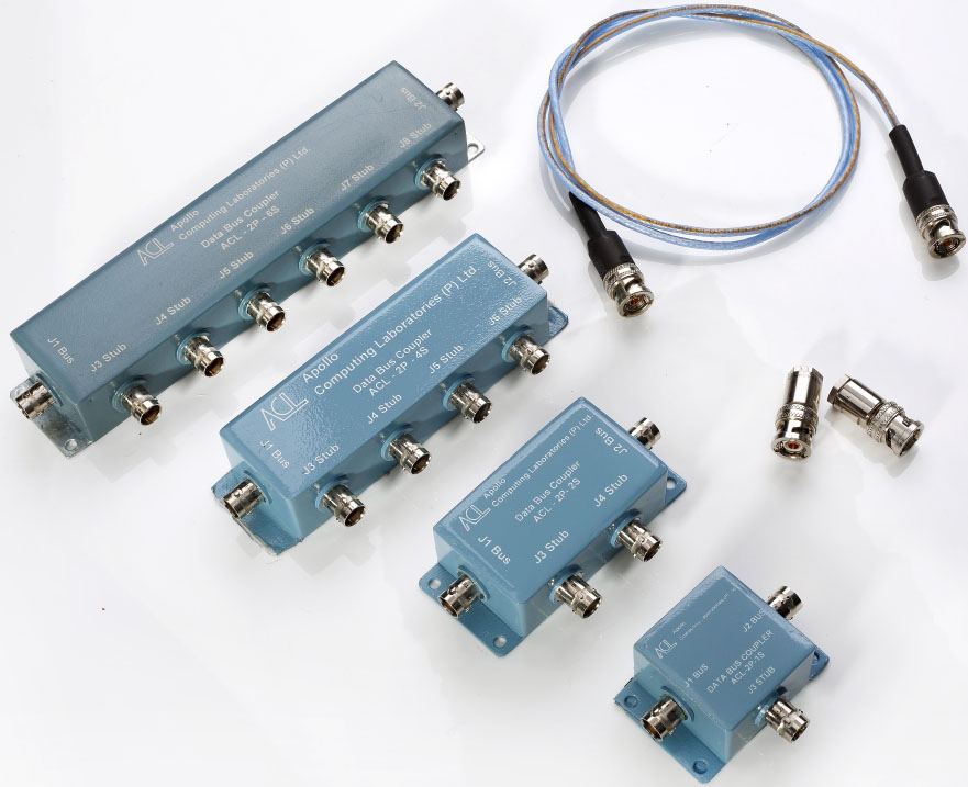
MIL-STD-1553B Multi-stub Bus Couplers Features
Industry standard connectors
Low cost
55db CMR
High EMI resistance
Flight quality units
Small volume
High reliability
Compatible with MIL-STD-1553B
Description
ACL manufactures a full range of Multi-stub couplers for MIL-STD-1553B with up to eight transformer coupled stub ports and industry standard connectors. These couplers are ideal for airborne applications and inexpensive enough for use in test and development applications. Fault isolation is provided between each stub and the bus.
Electrical Specifications (In accordance with MIL-STD-1553B, Notice -2)
Droop: 20% max at 250KHz.
Overshoot and ringing: less than 1.0V (peak with 100 ns rise and fall time).
Common mode rejection: >45 dB max. at 1.0 MHz.
Fault protection: 58.5 Ohms ± 2% resistor in series with each bus winding connection..
Stub voltage : 1.0V to 14.0V p-p (line-to-line signal voltage).
Transformer (MIL-T-21038 standard) : 1.41:1.
Isolation Resistor (MIL-R-39017 standard) : 59 ohm, 1 watt, 1% (non-inductive).
Operating Temperature :-55°C to +125°C.
Input Impedance : 3,000.0 Ohms minimum (75 kHz to 1MHz).
Mechanical Specifications
Connectors : Trompeter BJ-77 miniature 3- lug receptacle front mount or equivalent.
Case material: Tin plated CRCA Sheet.
Base Plate material : Tin plated CRCA Sheet.
Mounting/bottom surface : un-painted.
Color: Peacock blue.
Size and Weight for 2-Port 1-Stub (Typical values)
Size : 38mm W x 25.4mm H x 71mm L.
Weight : 100 grams (max).
Size and Weight for 2-Port 2-Stub (Typical values)
Size : 38mm W x 25.4mm H x 94mm L.
Weight : 160grams (max).
Size and Weight for 2-Port 4-Stub (Typical values)
Size : 38mm W x 25.4mm H x 140mm L.
Weight : 260 grams (max).
Other Optional Sizes as per requirement of Customers will be Provided.
Cables Technical Features
Twisted shielded MIL-STD-1553B cable.
Available in sizes of 6ft, 12 ft, 20 ft.
Optional : User definable sizes.
High reliability.
General Description
The data bus cable consists of two conductors twisted shielded pair (as specified in MIL-STD-1553B) fitted with Trompeter PL-75 (standard miniature TRB Bayonet plug, 3-lug, cable mount or equivalent) on both ends. The data bus cables are available in sizes of 6ft, 12ft and 20ft. In addition to these standard sizes, custom specified size data bus cables are also available (contact ACL for further details).
Terminators Features
Low cost.
Small size.
Rugged construction.
High reliability.
The data bus terminator provides bus terminations as specified in MIL-STD-1553B, when used in conjunction with ACL’s standard Data bus couplers.
Specifications
Connector : Trompeter PL-75 standard miniatureTRB Bayonet plug, 3-lug,cable mount or equivalant
Weight : 50 gms (max)
Size: 1.95”L x 0.6”D (max)
Termination Resistor (MIL-R-39017 standard): 75 ohm, 1 watt, 1% (non-inductive)
Operating Temperature : -55°C to +125°C
ACL-DBC-2P-1S : Data Bus Couplers Type 2-Port 1-Stub
ACL-DBC-2P-2S : Data Bus Couplers Type 2-Port 2-Stub
ACL-DBC-2P-4S : Data Bus Couplers Type 2-Port 4-Stub
ACL-DBC-2P-8S : Data Bus Couplers Type 2-Port 8-Stub
ACL-DBCBL-3F : MIL-STD-1553B Data Bus cable with PL-75 connectors on both ends with 3 feet length
ACL-DBCBL-6F : MIL-STD-1553B Data Bus cable with PL-75 connectors on both ends with 6 feet length
ACL-DBCBL-12F : MIL-STD-1553B Data Bus cable with PL-75 connectors on both ends with 12 feet length
ACL-DBCBL-20F : MIL-STD-1553B Data Bus cable with PL-75 connectors on both ends with 20 feet length
ACL-DBT : MIL-STD-1553B Data Bus 75 Ohms Terminator
Inline couplers
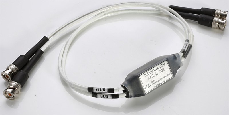
MIL-STD-1553B Multi-stub Inline Couplers Features
Comes with Industry standard connectors/Cable.
Low cost
55db CMR
High EMI resistance
Flight quality units
Small volume
High reliability
Compatible with MIL-STD-1553B
Description
ACL manufactures a full range of Multi-stub inline couplers for MIL-STD-1553B with up to Four transformer coupled stub ports. Inline Couplers comes with industry standard connectors as per user requirments (or) comes with default or selectable cable length in fts. These couplers are ideal for airborne, Missile and Naval applications. Fault isolation is provided between each stub and the bus.
Electrical Specifications (In accordance with MIL-STD-1553B, Notice -2)
Droop: 20% max at 250KHz.
Overshoot and ringing: less than 1.0V (peak with 100 ns rise and fall time).
Common mode rejection: >45 dB max. at 1.0 MHz.
Fault protection: 58.5 Ohms ± 2% resistor in series with each bus winding connection..
Stub voltage : 1.0V to 14.0V p-p (line-to-line signal voltage).
Transformer (MIL-T-21038 standard) : 1.41:1.
Isolation Resistor (MIL-R-39017 standard) : 59 ohm, 1 watt, 1% (non-inductive).
Operating Temperature :-55°C to +125°C.
Input Impedance : 3,000.0 Ohms minimum (75 kHz to 1MHz).
Mechanical Specifications
Connectors : Trompeter PL-75/DK-0621 series/optional user selectable.
Case material:Tin plated CRCA sheet.
Base Plate material : Tin plated CRCA sheet.
Surface Finish : Adhesive heat shrinkable sleeve with proper labling.
Cable: Double shielded Twinax Cable (as per JSS 51034 & JSS 51038/MIL-C-17/203 or Raychem 10614-9 or MIL-C-17/176-00002).
Bus/Stub Indication: Indicated with label.
Dimensions of Inline Couplers:
2-Port 1-Stub (Bus on both sides)
Size (W x H x L) : 15±0.5mm X 10±0.5mm X 53±0.5mm.
2-Port 1-Stub (Bus on same side)
Size (W x H x L) : 15±0.5mm X 10±0.5mm X 53±0.5mm.
1-Port 1-Stub (Stub and Bus on both sides)
Size (W x H x L) : 15±0.5mm X 10±0.5mm X 53±0.5mm.
1-Port 1-Stub (Stub and Bus on same side)
Size (W x H x L) : 15±0.5mm X 10±0.5mm X 40±0.5mm.
2-Port 2-Stub (Bus on both sides)
Size (W x H x L) : 15±0.5mm X 10±0.5mm X 74±0.5mm.
2-Port 2-Stub (Bus on same side)
Size (W x H x L) : 15±0.5mm X 10±0.5mm X 74±0.5mm.
1-Port 2-Stub (Stubs on both sides)
Size (W x H x L) : 15±0.5mm X 10±0.5mm X 74±0.5mm.
1-Port 2-Stub (Stubs on same side)
Size (W x H x L) : 15±0.5mm X 10±0.5mm X 74±0.5mm.
2-Port 3-Stub (Bus on both sides)
Size (W x H x L) : 27±0.5mm X 10±0.5mm X 78±0.5mm.
2-Port 3-Stub (Bus on same side)
Size (W x H x L) : 27±0.5mm X 10±0.5mm X 78±0.5mm.
1-Port 3-Stub (Stubs on both sides)
Size (W x H x L) : 27±0.5mm X 10±0.5mm X 78±0.5mm.
1-Port 3-Stub (Stubs on same side)
Size (W x H x L) : 27±0.5mm X 10±0.5mm X 78±0.5mm.
2-Port 4-Stub (Bus on both sides)
Size (W x H x L) : 27±0.5mm X 10±0.5mm X 78±0.5mm.
2-Port 4-Stub (Bus on same side)
Size (W x H x L) : 27±0.5mm X 10±0.5mm X 78±0.5mm.
1-Port 4-Stub
Size (W x H x L) : 27±0.5mm X 10±0.5mm X 78±0.5mm.
Inline Terminator
Size (W x H x L) : 15±0.5mm X 10±0.5mm X 40±0.5mm.
Note : Single port (1-Port) Coupler comes with internal termination (78 Ohms).
Other Optional Sizes as per requirement of Customers will be Provided.
ACL-ILC-2P-1S-B : Inline Coupler Type 2-Port 1-Stub (Bus on both sides)
ACL-ILC-2P-1S : Inline Coupler Type 2-Port 1-Stub (Bus on same side)
ACL-ILC-1P-1S-B : Inline Coupler Type 1-Port 1-Stub (Stub and Bus on both sides)
ACL-ILC-1P-1S : Inline Coupler Type 1-Port 1-Stub (Stub and Bus on same side)
ACL-ILC-2P-2S-B : Inline Coupler Type 2-Port 2-Stub (Bus on both sides)
ACL-ILC-2P-2S : Inline Coupler Type 2-Port 2-Stub (Bus on same side)
ACL-ILC-1P-2S-B : Inline Coupler Type 1-Port 2-Stub (Stubs on both sides)
ACL-ILC-1P-2S : Inline Coupler Type 1-Port 2-Stub (Stubs on same side)
ACL-ILC-2P-3S-B : Inline Coupler Type 2-Port 3-Stub (Bus on both sides)
ACL-ILC-2P-3S : Inline Coupler Type 2-Port 3-Stub (Bus on same side)
ACL-ILC-1P-3S-B : Inline Coupler Type 1-Port 3-Stub (Stubs on both sides)
ACL-ILC-1P-3S : Inline Coupler Type 1-Port 3-Stub (Stubs on same side)
ACL-ILC-2P-4S-B : Inline Coupler Type 2-Port 4-Stub (Bus on both sides)
ACL-ILC-2P-4S : Inline Coupler Type 2-Port 4-Stub (Bus on same side)
ACL-ILC-1P-4S : Inline Coupler Type 1-Port 4-Stub (Stubs on both sides)
ACL-ILT-78R : MIL-STD-1553B Moulded 78 Ohms Terminator
Note : Inline Coupler comes with 1ft cable length by default and variable lengths can be supplied as per user requirment.