Apollo Computing Laboratories (P) LtdInnovation is our Tradition
+91-40- 27141522, 27141533
RT-HILS Real–Time Hardware-In-Loop Simulation System

Electronic Control Units (ECUs) of platforms/plants need extensive testing in a realistic environment, in closed loop, at early stages of development. But, practical experiments can be very expensive and are often difficult to accomplish, as testing the behaviour of the Control Unit in extreme manoeuvres or failure situations is often dangerous and may not be comprehensive.
Hardware-In-Loop Simulation (HILS) provides a standard approach to replace test experiments and thus reduce development cost & time. With HILS, the Control Units are tested and compared in closed loop with real-time simulation models replacing the platforms such as: Launch vehicles, Air crafts, Missiles, Tanks, Torpedoes, Satellites etc.
The real-time speed of the simulated platform/plant can be achieved by high performance Processor boards for number crunching associated with the simulation model(s) and high speed, high resolution I/O boards for interface with outside world.
The RT-HILS developed by ACL provides the real-time hardware & software environment for accomplishing the dynamics of HILS.
The System has been conceived taking into account the generic capabilities desired for Real - time HILS applications. It's configuration is realised to adopt State of art Technology, open System Architecture, comply with standards and to provide robustness & reliability through Judicious mix of Commercial-of-the -Shelf Products and signal conditioning designs.
The standard ready-to-use configuration of the RT-HILS is shown in figure below.
Enclosure : 13 - slot VXI Main frame & 19" sub-frames on 19" rack
Processors : Dual Embedded Pentium controllers each working @ 450 MHz, 192MB RAM, 4GB HDD, 3 ½" FDD, AGP Video, Real-time Clock, Watch-dog Timer, Counters, USB, Serial, Parallel, SCSI & PC Card Interface, 10/100T Ethernet, PCI local Bus Interface, VxWorks kernel, VXI-VISA Software, VxWorks drivers for I/O.
Input/ Output: Multifunction I/O, 1.25MS/s, 12 bit, 64 channel Analog Inputs, 2 channel Analog Outputs, 8 Digital I/Os, 24-bit counters. 16 channel 12 bit DAC with settling time of 5 msec, 128 - channel I/O with 64 - output channels each with 250mA sink up to 42V and 64 Input channels with ± 42V with threshold settable in 250mV steps. PCI based 8 channel 460K Baud RS-422 with T/R FIFO.
Optional: Three MIL-STD-1553B BC/RT/MT nodes with simulation Monitoring , Software , ARINC-429 interfaces (3 Tx & 8 Rx)
Conditioning: Galvanic isolation for Analog, opto-isolation for Digital signals.
Protection : Over-voltage, Over-current, Over-temperature protections.
Mode(s) : Master / slave, load sharing, parallel tasking, dual port transactions and bus mastering.
High Lights
| Parameter | ACL's RT - HILS | AD-100 BASED HILS |
|---|---|---|
| Input - Output for 6 - DOF | 300 msec | 700 - 800 msec |
| ADC/DAC accuracies | 20 mV | 50 - 70 mV |
| Aircraft 6 - DOF with I/O | 2 msec | 6.25m sec |
| Growth Potential | Very high | Limited |
| Architecture | Programmable & Configurable | Tightly coupled |
| Embargo | Indigenous | Yes |
Potential
The system has growth potential to accommodate additional or different I/Os, which may be specific to the environments. The system can be customised for typical physical, electrical and functional necessities of applications, as well as fine-tuned to achieve the desired real-time performance.
Application
This system has been customised by Aeronautical Development Agency (ADA) for the real-time Flight Dynamics Simulator (FDS) functionality to achieve 1.3 msec single step integration performances.
ACL sincerely acknowledges the technical cooperation extended by ADA during the development of the system for the application.
Approach
ACL can take the single-window responsibility for system study and customisations of the standard product or can participate in evolving any specific application oriented design & development.
Your queries may be addressed to us, in response to which, it shall be endeavoured to provide the desired information and effectively participate in your programmes.
ACL-RT-HILS : RT - Hardware - In - Loop Simulation System *
* ACL is continuously working on improvements of its products; hence these specifications are subject to change without any notice. wherever the products are updated, the updated/revised version will be supplied.
Test-Jig for Missile Interface Unit
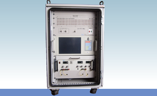
INTRODUCTION :
MIU Test-Jig is used for the Functional testing of Missile Interface Unit. This Test Simulator Comprises of a standard 19" Rack fitted with an Industrial Computer, Relay box and linear Power Supply.
Industrial PC :
The Test-Jig is configured around an Industrial PC. The Industrial PC has a 12.1" Monitor as well as fully featured Keyboard and Mouse. The PC is equipped with PCI based Add-on cards as ADC Card, DAC Card, 1553B Card and RS-422 Card.
Relay Box :
The Relay Box consists of a Relay PCB and LED PCB.The Relay PCB consists of 98 Relays.The Relays are used to load the MIU Digital O/P's.it is a double ploe double through(DPDT),Compact high performance,direct PCB mountable type and dust protected relay.
Regulated DC Power Supply:
I/P : 230V AC, 50 Hz
O/P 1 : 0 – 32V DC / 2 Amps
O/P 2 : 5V DC / 5 Amps
O/P 3 : ± 15V DC / 0.5 Amps
Display and Control Panel:
It consists of latchable Push Button Switches to Control the Power to MIU & Test-Jig
A non-latchable Push Button Switch to reset MIU.
119”Rack, 17U Height, 24”Width, 24”depth, 35”Height
Power Requirement : 230V Single Phase AC
Power Consumption : < 2.0A on 230V, Single Phase
Test-Jig for Weapon Computer System

INTRODUCTION :
The Test-Jig is used for testing Stores Interface Box. This is the System Test-Jig comprising of a Standard 19” Rack fitted with an Industrial Computer, Matrix Patch Panel, Dual Output Power Supply and RF Signal Generator along with Test Panel
Industrial PC:
The Test-Jig is configured around an Industrial PC. The Industrial PC has a membrane Keypad as well as fully featured keyboard and mouse. The PC is equipped with Four add-on Cards as DI Card, DO Card, RS422 Card, 1553B Card
Matrix Patch Panel:
It is divided into 4 blocks viz., M1, M2, M3 and M4. Each block consists of 8 Rows & 10 Columns (i.e., 80 connections per block). The DI / DO and Display Control Panel signals are terminated onto a Matrix Patch Panel for easy access of measurement and troubleshooting
Relay Box:
The Relay Box consists of a Relay PCB and LED PCB.The Relay PCB consists of 98 Relays.The Relays are used to load the MIU Digital O/P's.it is a double ploe double through(DPDT),Compact high performance,direct PCB mountable type and dust protected relay.
DC Power Supply: 32V Dual Output @ 10A
RF Generator:
Test Jig Generates RF signals. These signals are the source RF input signals to the SIB. The RF Generator will generate the required RF-LB,RF-HB1 & RF-HB3 signals for the RF Module of SIB. Frequency range is upto 20 MHz.
Test jig Rear Side:
The Circular Connector Panel and Power Supply ON-OFF switch are provided at the Rear side of the Test-Jig.
19” rack, 30U of Vero President (1500 Height x 600 Width x 600 Depth)
Power Requirement :230V Single Phase, AC
Power Consumption : < 4.0A, on 230V, Single Phase
UPS : 30 Minutes Backup for Industrial PC